
Laser cladding method for mining hydraulic support column and mining stainless steel hydraulic column

A technology of hydraulic support columns and laser cladding, which is applied in the direction of pillars/supports, laser welding equipment, mining equipment, etc., can solve the problems of poor wear resistance of the coating, corrosion of columns, peeling and peeling of the coating, and achieve Improved anti-corrosion performance, extended service life, and strong bonding effect

Inactive Publication Date: 2011-11-16
SHANDONG ENERGY HEAVY EQUIP GRP DAZU REMANUFACTURING CO LTD +1
View PDF3 Cites 35 Cited by
  • Summary
  • Abstract
  • Description
  • Claims
  • Application Information

AI Technical Summary

Problems solved by technology

[0003] In mining production, in order to ensure the production safety of the mine road, it is necessary to use the mine hydraulic support for support in the mine road. The mine hydraulic column is an important supporting part in the hydraulic support. In the existing mine hydraulic column In order to prolong the service life of the column and reduce the corrosion of the surface of the column, the surface plating method is usually used to prevent rust and corrosion on the surface. Due to the poor wear resistance of the plating layer, its service life is 1-1.5 years. The iron layer is prone to peeling and peeling, so that the emulsion will corrode the surface of the column, affect the use effect of the hydraulic support, and greatly reduce the service life of the mining hydraulic column

Method used


Image

  • Laser cladding method for mining hydraulic support column and mining stainless steel hydraulic column
  • Laser cladding method for mining hydraulic support column and mining stainless steel hydraulic column

Examples


Embodiment Construction

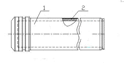
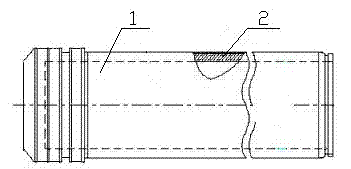
[0018] Accompanying drawing is the first embodiment of the present invention, this embodiment is described in detail in conjunction with accompanying drawing, is used for the first embodiment of the laser cladding method of mining hydraulic support column, and its steps are:

[0019] A. Clamp the live column of the column body 1 that has been derusted, leveled and textured to the laser processing machine tool, so that the live column of the column body 1 is driven by the main shaft C to rotate at a speed of 0.5 rpm. A laser head and a nickel-based alloy powder output nozzle are provided on the axial centerline of the live column of the column body 1. The laser head and the powder feeder move at a speed of 0.05 mm / s on the X linear axis. A laser cladding layer 2 with a thickness of 0.4mm is formed on the living column of the body 1, and the overlapping ratio of adjacent laser cladding layers 2 is set to 50%.

[0020] B. The laser beam is focused by the integrating mirror to for...


PUM

PropertyMeasurementUnit
thicknessaaaaaaaaaa
thicknessaaaaaaaaaa
thicknessaaaaaaaaaa

Abstract

The invention relates to a laser cladding method for a mining hydraulic column and a mining hydraulic column. The laser cladding method for a mining hydraulic column comprises the steps as follows: a laser beam and a nickel-based alloy powder stream output by a powder feeder are utilized to form helical scanning along the surface of a movable column of a column body 1; the section of the laser beam output by a laser head is set into a (15-20mm)*(1.5-2.5mm) rectangular spot, the scanning linear velocity of the laser beam is set at 480-720 mm / min, and the output power of the laser for outputting the laser beam is set at 7200-7400 W, wherein the nickel-based alloy powder output by the powder feeder contains the following components in percentage by weight: not more than 0.15% of C, 0.5-1.0% of Si, 0.4-0.8% of Mn, 17.5-19.5% of Cr, 21-25% of Ni and the balance of Fe; and a mining hydraulic column with a laser cladding layer (2) which has a thickness of 0.4-0.7 mm and is formed by laser cladding of the nickel-based alloy powder is arranged on the movable column of the column body (1). Thus, the service life of the column is prolonged.

Description

[0001] 1. Technical field [0002] The invention relates to a laser cladding method for a mining hydraulic support column and a mining stainless steel hydraulic column, in particular to a mining stainless steel hydraulic column suitable for use in mines where the pH exceeds the standard. 2. Background technology [0003] In mining production, in order to ensure the production safety of the mine road, it is necessary to use the mine hydraulic support for support in the mine road. The mine hydraulic column is an important supporting part in the hydraulic support. In the existing mine hydraulic column In order to prolong the service life of the column and reduce the corrosion of the surface of the column, the surface plating method is usually used to prevent rust and corrosion on the surface. Due to the poor wear resistance of the plating layer, its service life is 1-1.5 years. The iron layer is prone to peeling and peeling, so that the emulsion will corrode the surface of the ...

Claims


Application Information

Patent Timeline
Patent Type & Authority Applications(China)
IPC IPC(8): C23C24/10B23K26/34E21D15/44
CPCE21D15/44C23C24/106B23K26/34C23C24/10E21D15/50
Inventor 李希勇李伦实周峰杜柏奇杨庆东苏伦昌澹台凡亮董春春
Owner SHANDONG ENERGY HEAVY EQUIP GRP DAZU REMANUFACTURING CO LTD
Learn More