Interference source determination method and system
A technology of interference source and interference indication, applied in electrical components, wireless communication, etc., can solve the problems of inability to accurately determine the interference source, inability to determine the interference source, and inability to accurately determine whether the interference source has actually caused interference, etc., to improve judgment Precision, precisely determined results
- Summary
- Abstract
- Description
- Claims
- Application Information
AI Technical Summary
Problems solved by technology
Method used
Image
Examples
Embodiment 1
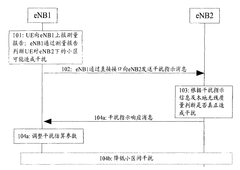
[0055] This embodiment describes the situation where there is a direct interface in the LTE system, specifically the situation where an interference indication is sent through the X2 interface, such as image 3 shown. The source base station eNB1 predicts that the UE under the jurisdiction of Cell1 will cause uplink interference to the Cell2 under the jurisdiction of the target base station eNB2. eNB1 and eNB2 can be macro base stations or home base stations, and there is a direct interface such as X2 between eNB1 and eNB2. The direct interface may be established on the connection between eNB1 and eNB2. If eNB2 is a home base station that accesses the core network through a home base station gateway, the direct interface can also be established on the connection between eNB1 and the home base station gateway of eNB2 and the connection between the home base station gateway and eNB2; The base station gateway accesses the home base station of the core network, and the direct int...
Embodiment 2
[0067] This embodiment describes the situation where there is a direct interface in the UMTS system, specifically the situation where an interference indication is sent through the Iur interface, such as Figure 4 shown. The source network element RNC1 predicts that the UE under the jurisdiction of the cell Cell1 will cause uplink interference to the Cell2 under the jurisdiction of the target network element RNAC2. RNC1 and RNC2 may be ordinary macro RNCs or home base stations. In this embodiment there is a direct interface Iur between RNC1 and RNC2. The Iur interface can be established on the connection between RNC1 and RNC2; if RNC2 is a home base station connected to the core network through a gateway, it can also be established on the connection between the gateway of RNC1 and RNC2 and the connection between the gateway and RNC2; if RNC1 is a home base station connected to the core network through a gateway, and may also be established on the connection from RNC1 to the g...
Embodiment 3
[0069] This embodiment describes the situation of forwarding the interference indication information through the core network in the LTE system, specifically the situation of sending the interference indication through the MME, such as Figure 5 shown. The source base station eNB1 predicts that UEs under the jurisdiction of Cell1 cause uplink interference to Cell2 under the jurisdiction of the target base station eNB2. eNB1 and eNB2 can be macro base stations or home base stations. S1 is established between eNB1 and eNB2 and the core network element MME. interface. If eNB1 is a home base station connected to the core network through the home base station gateway, this S1 interface can also be established between eNB1 and the home base station gateway and between the home base station gateway and the MME; if eNB2 is connected to the core network through the home base station gateway The home base station, the S1 interface may also be established between the eNB2 and the home b...
PUM
 Abstract
Description
Claims
Application Information
 - R&D
- Intellectual Property
- Life Sciences
- Materials
- Tech Scout
- Unparalleled Data Quality
- Higher Quality Content
- 60% Fewer Hallucinations
Browse by: Latest US Patents, China's latest patents, Technical Efficacy Thesaurus, Application Domain, Technology Topic, Popular Technical Reports.
© 2025 PatSnap. All rights reserved.Legal|Privacy policy|Modern Slavery Act Transparency Statement|Sitemap|About US| Contact US: help@patsnap.com


