Electronic heating module

An electronic and heating body technology, applied in circuits, electric light sources, electrical components, etc., can solve the problems of high manufacturing cost and difficult control of manufacturing quality, and achieve the effects of low cost, simple structure and good heat dissipation performance.

Inactive Publication Date: 2011-11-09
OSRAM GMBH
View PDF0 Cites 0 Cited by
  • Summary
  • Abstract
  • Description
  • Claims
  • Application Information

AI Technical Summary

Problems solved by technology

[0005] A technical solution of pressing the copper core onto the FR-4 board has been proposed in the prior art, but the manufacturing cost of this solution is still high, and the manufacturing quality is difficult to control

Method used


Image

  • Electronic heating module
  • Electronic heating module
  • Electronic heating module

Examples


Embodiment Construction

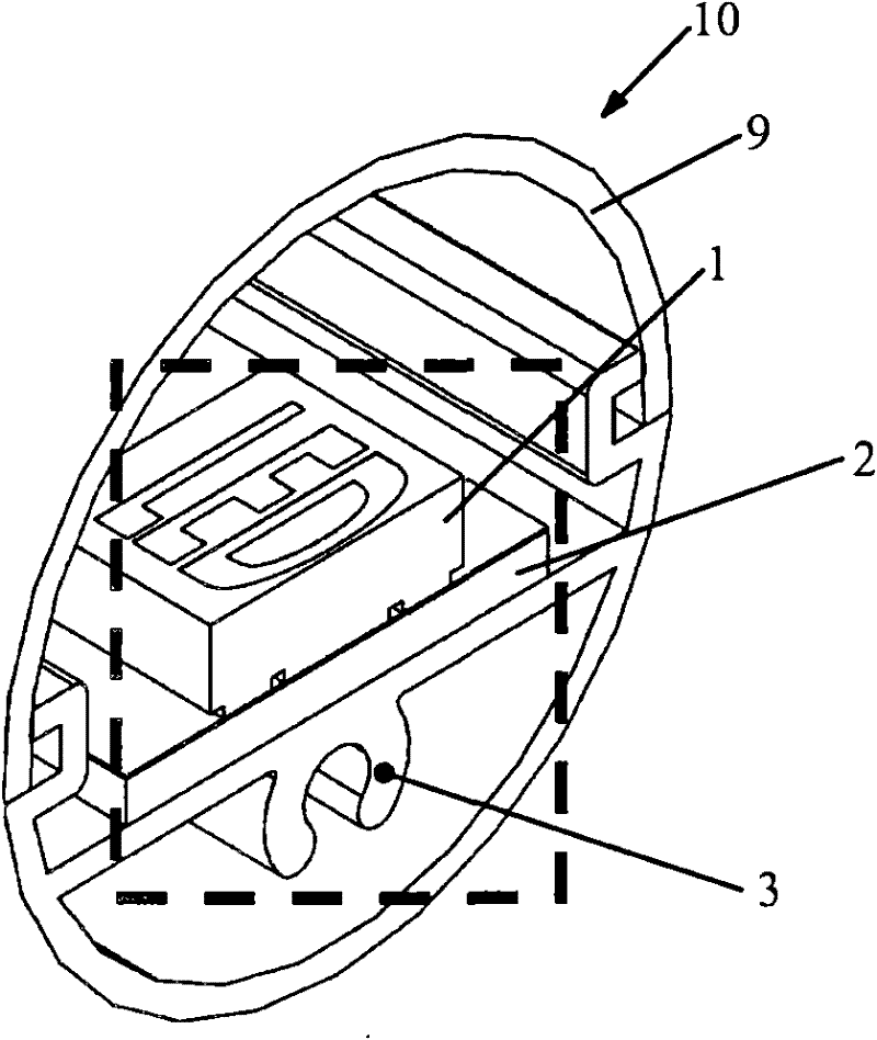
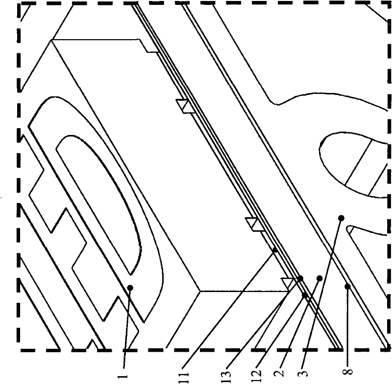
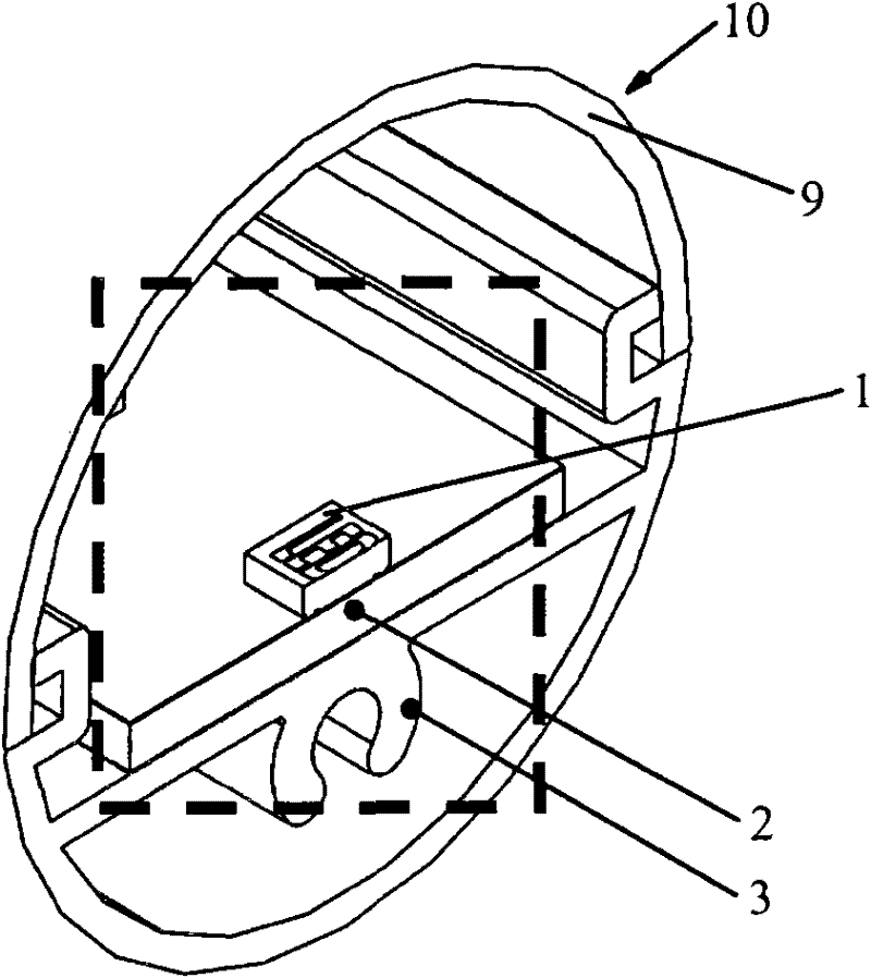
[0021] Figure 3a , 3b respectively show a schematic diagram of an electronic heating module designed as an LED module according to the first embodiment of the present invention and Figure 3a Enlarged view at the dotted line. It should be pointed out that although an LED module is used as an example here, the electronic heating module is not limited to a light emitting module, and it can be any electronic module that generates heat to achieve other functions. The light emitting module is not limited to the LED module, and it can be any module capable of emitting light.

[0022] From Figure 3a , 3b, it can be seen that the LED module includes a light cover 9 and at least one LED 1 , a substrate 2 and a heat sink 3 disposed in the light cover 9 . Here, the substrate 2 may be a substrate with poor thermal conductivity, such as an FR-4 substrate.

[0023] Different from the prior art, a through hole 4 penetrating through the thickness of the substrate 2 in the vertical direc...


PUM


Abstract

The invention relates to an electronic heating module (10), which comprises an electronic heating body (1), a substrate (2) and a heat sink (3), wherein the electronic heating body (1) is arranged on the substrate (2). The electronic heating module is characterized in that: a through hole (4) is formed in the substrate (2); the heat sink (3) comprises a first part (5) and a second part (6); the first part (1) is arranged below the substrate (2); and the second part (6) is arranged in the through hole (4). The invention can provide the electronic heating module (10), particularly a light emitting module, which is low in cost, simple in structure and good in radiation performance.

Description

technical field [0001] The present invention relates to an electronic heating module, especially a light-emitting module, and further relates to an LED module. Background technique [0002] The LED is a widely used light source, and it is also a light source with a long service life. LEDs need to have an appropriate temperature condition when they are working normally. If the temperature exceeds this temperature, the performance of the LED will be affected, and the advantage of its long life may be lost. Therefore, how to conduct the heat generated by the LED chip, especially after the circuit board is installed, can still be well conducted has become an important research hotspot. At the same time, this is also the problem faced by other electronic heating modules. [0003] In the current LED module or lamp structure, the LED must be placed on the MCPCB (Metal Core Printed Circuit Board) to dissipate the heat generated by the LED. see Figure 1a , 1b, Figure 1a , 1b sho...

Claims


Application Information

Patent Timeline
Patent Type & Authority Applications(China)
IPC IPC(8): H01L33/48H01L33/62H01L33/64F21S2/00F21Y101/02
CPCF21V29/004F21Y2101/02F21K9/00F21V29/507F21V29/51F21V29/74F21V29/89F21V29/90F21Y2115/10
Inventor 李皓刘晴叶泽生杨灿邦
Owner OSRAM GMBH
Why Eureka
Try Eureka