Jack frame and manufacturing method thereof

A jack and frame technology, applied in the direction of lifting devices, etc., can solve problems such as high cost, easy to twist or deform, and unable to bear heavy loads

Inactive Publication Date: 2011-11-09
伊恩·梅赛森 +1
View PDF5 Cites 2 Cited by
  • Summary
  • Abstract
  • Description
  • Claims
  • Application Information

AI Technical Summary

Problems solved by technology

Once this frame structure bears a heavy load, it is easy to distort or deform, because the structure lacks a bottom surface at this time, so that the cross section of the frame is only two parallel lines, not a box shape, which

Method used


Image

  • Jack frame and manufacturing method thereof
  • Jack frame and manufacturing method thereof
  • Jack frame and manufacturing method thereof

Examples


Embodiment Construction

[0028] Embodiments of the present invention will be described in detail below in conjunction with the accompanying drawings, so that the features and principles of the present invention will be clearer. Of course, the essence of the present invention is not limited by this embodiment.

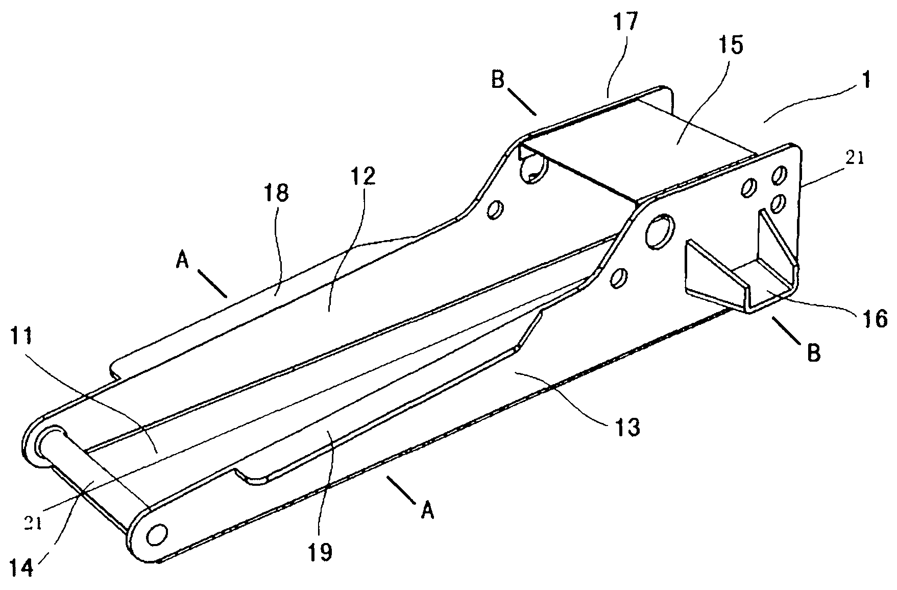
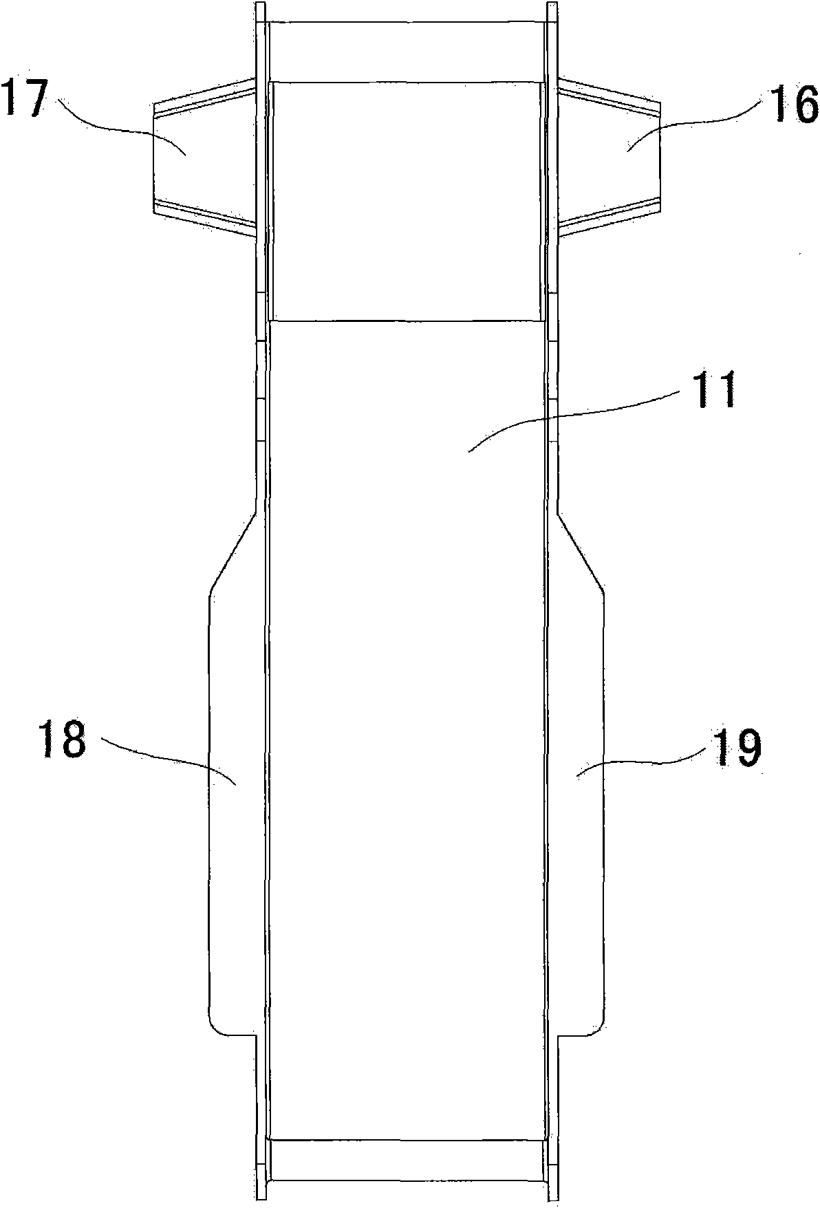
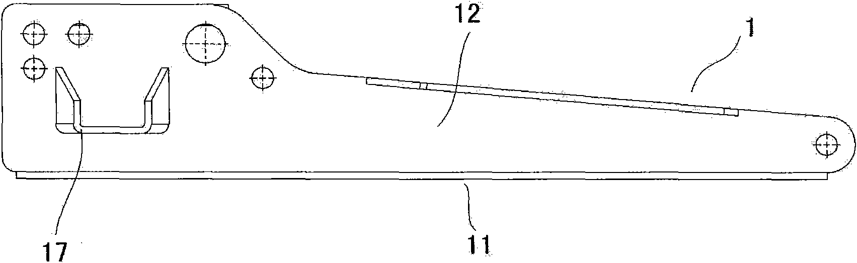
[0029] See attached Figure 1-5 , The jack frame 1 of the present invention includes two side walls 12 , 13 , a bottom surface 11 and an upper surface 15 . Two sides of the bottom surface 11 are respectively connected with the above-mentioned side walls 12 and 13 . One end of above-mentioned side wall 12,13 links to each other with support bar 14 respectively, and this support bar is a round bar or other bar, and each end of it passes through the inner surface of above-mentioned side wall 12,13, for example welds or tightly fit fastening way, interconnected. In addition, the other ends of the side walls 12 and 13 are connected to the upper surface 15 . The above-mentioned side walls 12, 13 ...


PUM


Abstract

The invention provides a jack frame, comprising two side walls and one bottom surface which is respectively connected with the two side walls, wherein the bottom surface and the two side walls are formed by bending a flat material. The jack frame provided by the invention is provided with the bottom surface, thus the section of the jack frame which is vertical to a longitudinal axis is rectangular or square, and the overall structure has fastness and can support a heavier load. Besides, more time is saved for processing the jack frame as the main structure of the jack frame is formed by stamping, shearing or bending a single flat material. No welding is used in the main structure frame (the bottom surface and the side walls are directly processed by a whole plate), thus the jack frame provided by the invention is firmer compared with the traditional welding frame.

Description

technical field [0001] The invention relates to a jack, in particular to a jack frame and a manufacturing method thereof. Background technique [0002] Lifting jacks generally consist of a base frame or base on which pneumatic or hydraulic equipment for lifting a load can be mounted. It is generally required that the frame is strong enough to support a heavy load. Existing frames are of a type having at least four individual parts joined, eg welded together, these four individual parts being two sides (walls), an upper surface and a bar. Once this frame structure bears a heavy load, it is easy to distort or deform, because the structure lacks a bottom surface at this time, so that the cross section of the frame is only two parallel lines, not a box shape, which is too weak to bear the load load. In addition, the welding or other connection of the above-mentioned individual parts is also a complex operation, which entails high costs, and this connection also leads to a wea...

Claims


Application Information

Patent Timeline
IPC IPC(8): B66F3/00B66F13/00
Inventor 伊恩·梅赛森
Owner 伊恩·梅赛森
Why Eureka
Try Eureka