
Brake cylinder

A brake cylinder and cylinder technology, which is applied in the field of brake cylinders, can solve the problems of brake cylinders with cumbersome structure, many connection activities, and large space structure, and achieve the effects of compact structure, reduced axial space, and beautiful appearance

Inactive Publication Date: 2011-11-02
ZHAOQING ZHICHENG PNEUMATIC
View PDF6 Cites 5 Cited by
  • Summary
  • Abstract
  • Description
  • Claims
  • Application Information

AI Technical Summary

Problems solved by technology

It consists of a cylinder body, a front gland and a rear gland placed at both ends of the cylinder body connected together, a piston rod and a piston placed in the cylinder body with one end extending out of the cylinder body through the front gland, respectively Placed between the piston and the cylinder body, between the cylinder body and the front gland, and between the piston rod and the front gland, there is an O-shaped sealing ring. The structure of the brake cylinder with this structure is cumbersome and the space structure is large. Inconvenient, because there are many connection activities between the parts of the cylinder, the airtightness is not good, and the service life is short

Method used


Image

  • Brake cylinder
  • Brake cylinder

Examples


Embodiment Construction

[0009] In order to facilitate the understanding of those skilled in the art, the floor spring of the present invention will be further described below in conjunction with the drawings and specific embodiments:

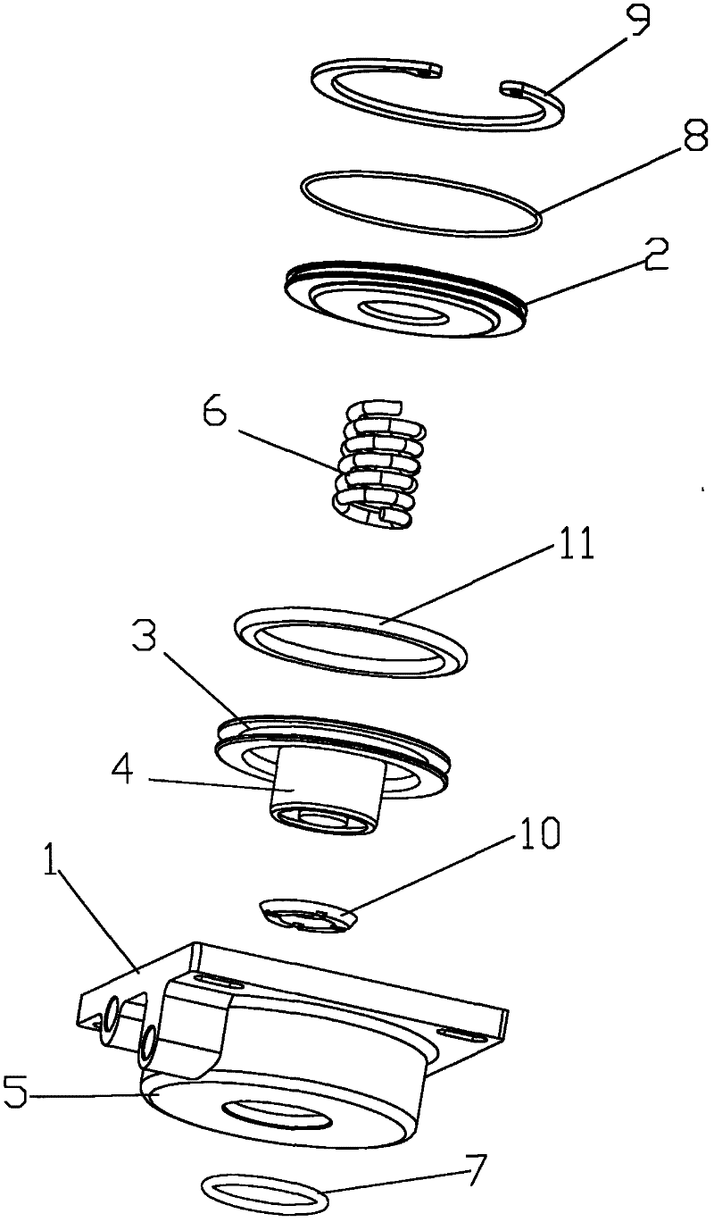
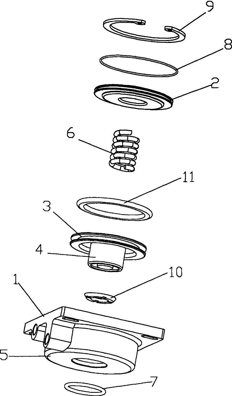
[0010] as attached figure 1 As shown, a brake cylinder includes a cylinder body 1 and a rear cover 2, and a cylinder core is provided in the cylinder body 1. The cylinder core includes a piston 3 and a piston rod 4, which is an integrated structure: the cylinder body 1 is a die-cast integrated structure including a front cover 5; the piston rod of the cylinder core is a hollow structure with a spring 6 inside. The front cover end of the cylinder block 1 is provided with an "O-shaped" rod ring 7 for sealing and guiding the piston rod, and a piston ring 11 for sealing the piston is provided on the piston 3 . The said rear cover 2 is provided with an "O" ring 8 and a snap ring 9 . The end of the piston rod 4 of the cylinder core is provided with a brake pad 10 made of n...


PUM


Abstract

The invention discloses a brake cylinder comprising a cylinder body and a rear cover, wherein the cylinder body is internally provided with a cylinder core; the cylinder core comprises a piston and a piston rod and is of an integral structure; the cylinder body is in an integral structure which contains a front cover and is molded through casting; and the piston rod of the cylinder core is in a hollow structure in which a spring is arranged. The brake cylinder is a single-action introduced-in ultrathin cylinder, has the advantages of simple structure, beautiful appearance, safety, reliability and long service life.

Description

technical field [0001] The invention relates to the field of pneumatic technology, in particular to a brake cylinder. Background technique [0002] Existing brake cylinders that are mainly used on woodworking machinery equipment make the brake pads at the shaft end firmly lock the moving machinery by the spring force of the cylinder so that they cannot move. It consists of a cylinder body, a front gland and a rear gland placed at both ends of the cylinder body connected together, a piston rod and a piston placed in the cylinder body with one end extending out of the cylinder body through the front gland, respectively Placed between the piston and the cylinder body, between the cylinder body and the front gland, and between the piston rod and the front gland, there is an O-shaped sealing ring. The structure of the brake cylinder with this structure is cumbersome and the space structure is large. Inconvenient, it is because there are many connection activities of each part of...

Claims


Application Information

Patent Timeline
Patent Type & Authority Applications(China)
IPC IPC(8): F15B15/14F15B15/20
Inventor 陈礼才
Owner ZHAOQING ZHICHENG PNEUMATIC
Learn More