
On-vehicle recorder

A vehicle-mounted recorder and vehicle diagnosis technology, which is applied in the direction of instruments, registration/indications, time registers, etc., can solve the problems of remote monitoring of vehicle running status, reduce the risk of data loss, and solve vehicle problems

Inactive Publication Date: 2011-10-19
CHERY AUTOMOBILE CO LTD
View PDF5 Cites 9 Cited by
  • Summary
  • Abstract
  • Description
  • Claims
  • Application Information

AI Technical Summary

Problems solved by technology

[0005] In order to solve the problem that the vehicle running status cannot be remotely monitored through the vehicle recorder, the embodiment of the present invention provides a vehicle recorder

Method used


Image

  • On-vehicle recorder
  • On-vehicle recorder
  • On-vehicle recorder

Examples


Embodiment 1

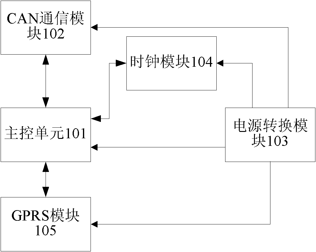
[0014] see figure 1 , the vehicle recorder in this embodiment includes a main control unit 101, a CAN communication module 102, a power conversion module 103, a clock module 104 and a GPRS (General Packet Radio Service, general packet radio service technology) module 105. Wherein, the CAN communication module 102 is used for obtaining the CAN signal from the vehicle diagnosis port; the main control unit 101 is used for receiving and processing the CAN signal obtained by the CAN communication module 102 to obtain vehicle condition information; the GPRS module 105 is used for connecting the main control unit 101 The obtained vehicle status information is uploaded to the host computer system, and the instructions from the host computer system are sent to the main control unit 101; the clock module 104 is used to provide a clock signal to the main control unit 101; the power conversion module 103 is used to diagnose the slave vehicle After conversion, the power signal obtained by ...

Embodiment 2

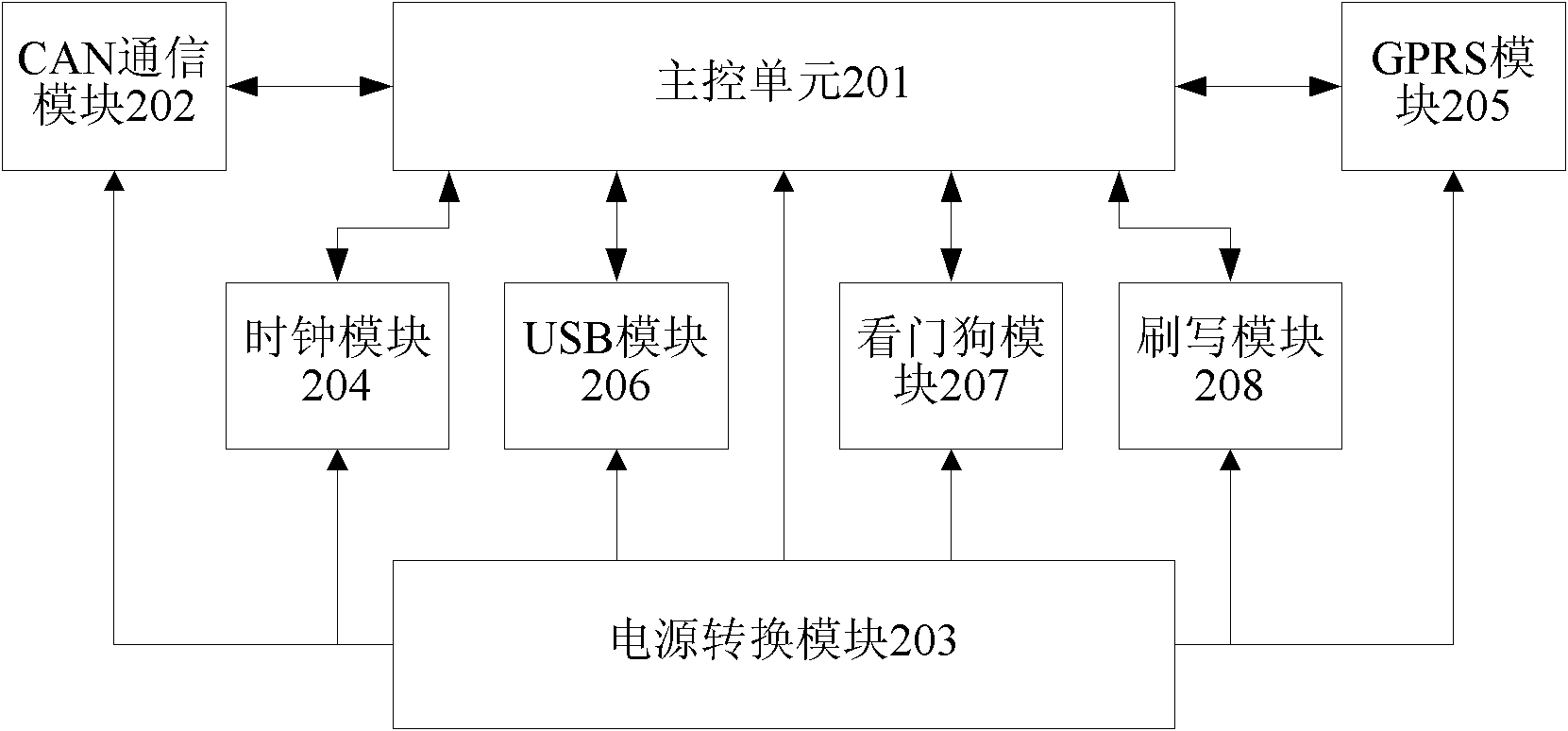
[0017] see figure 2 , the vehicle recorder in this embodiment includes a main control unit 201 , a CAN communication module 202 , a power conversion module 203 , a clock module 204 and a GPRS module 205 . The CAN communication module 202 is connected with the main control unit 201 and the vehicle diagnosis port, the input end of the power conversion module 203 is connected with the vehicle diagnosis port, and the output end of the power conversion module 203 is connected with the main control unit 201, the CAN communication module 202, the clock module 204 and the The GPRS module 205 is connected, the clock module 204 is connected to the main control unit 201 , and the GPRS module 205 is connected to the main control unit 201 .

[0018] Concretely, the CAN communication module 202 obtains the CAN signal from the vehicle diagnosis port, and sends the CAN signal to the main control unit 201; the main control unit 201 receives the CAN signal and processes the vehicle status info...


PUM


Abstract

The invention discloses an on-vehicle recorder, which belongs to the field of vehicle electronics. The on-vehicle recorder comprises a controller area network (CAN) communication module, a master control unit, a general packet radio service (GPRS) module, a clock module and a power supply conversion module, wherein the CAN communication module is used for acquiring a CAN signal from a vehicle diagnosis interface; the master control unit is used for receiving and processing the CAN signal acquired by the CAN communication module to obtain vehicle condition information; the GPRS module is used for uploading the vehicle condition information obtained by the master control unit to an upper computer system and transmit a command from the upper computer system to the master control unit; the clock unit is used for providing a clock signal for the master control unit; and the power supply conversion module is used for converting a power supply signal acquired from the vehicle diagnosis interface, and providing the converted power supply signal to the CAN communication module, the master control unit, the GPRS module and the clock module. The on-vehicle recorder uploads the vehicle condition information through the GPRS module; other users or managers can acquire the vehicle condition information remotely so as to perform remote real-time monitoring on the vehicle condition information and help a driver to solve vehicle problems in real time.

Description

technical field [0001] The invention relates to the field of automotive electronics, in particular to a vehicle recorder. Background technique [0002] The vehicle recorder is a special digital electronic recording device, which can record and store the vehicle speed, time, mileage and other state information about the vehicle in real time, and then realize the data output through the USB or RS232 interface. Existing on-board recorders usually output data through a USB port, and the user copies the vehicle status data through an external memory, such as a U disk, and finally analyzes the data on a computer to obtain the running status of the vehicle. [0003] In the process of realizing the present invention, the inventor finds that there are at least the following problems in the prior art: [0004] The vehicle-mounted recorder in the prior art needs to use a large-capacity external memory to copy the vehicle status information data to the computer for analysis, and cannot...

Claims


Application Information

Patent Timeline
IPC IPC(8): G07C5/00H04L29/08
Inventor 李延庆
Owner CHERY AUTOMOBILE CO LTD
Learn More