condenser

A condenser and refrigerant technology, applied in evaporators/condensers, refrigerators, refrigeration components, etc., can solve problems such as insufficient gas-liquid separation performance, waste of space in the engine room, and inability to save space, and achieve gas-liquid Good separation effect and space-saving effect

Active Publication Date: 2015-11-25
MAHLE INT GMBH
View PDF4 Cites 0 Cited by
  • Summary
  • Abstract
  • Description
  • Claims
  • Application Information

AI Technical Summary

Problems solved by technology

[0005] In the condenser described in the above publication, in order to effectively separate the gas and liquid in the first liquid collecting tank, it is necessary to make the inner volume of the first liquid collecting tank considerably larger than that of the second liquid collecting tank, so the first set The thickness of the liquid tank is considerably larger than that of the second liquid collecting tank, so there is a problem that a large space is required for arranging the condenser
[0006] In addition, other equipment is usually arranged near the condenser, but according to the condenser described in the above publication, the first liquid collection tank becomes an obstacle to other equipment.
For example, a radiator is usually arranged on the downstream side of the ventilation direction of the condenser for automobile air conditioners, but according to the condenser described in the publication, the first liquid collecting tank will become an obstacle to the installation of the radiator, and wasteful waste will be generated in the engine room. space, no space savings
In addition, since the heat exchange tube is connected to the first liquid collecting tank substantially in the entire length, there is a problem that the gas-liquid separation performance is insufficient.

Method used


Image

  • condenser
  • condenser
  • condenser

Examples


Embodiment Construction

[0046] Hereinafter, embodiments of the present invention will be described with reference to the drawings.

[0047] In the following description, the downstream side of the ventilation direction ( figure 1 the inside of the paper, image 3 and Figure 4 The upper side) is the front, and the opposite side is the back.

[0048] In addition, in the following description, the term "aluminum" includes not only pure aluminum but also aluminum alloys.

[0049]In addition, the same part and the same member are attached|subjected with the same code|symbol in all drawings, and repeated description is abbreviate|omitted.

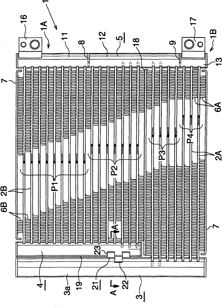
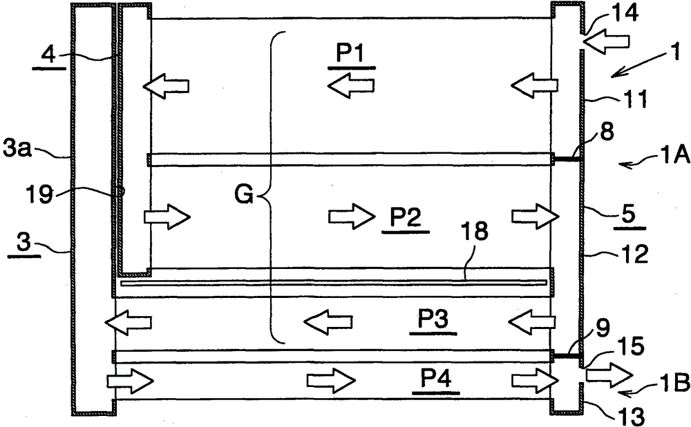
[0050] figure 1 Concretely showing the overall structure of the first embodiment of the condenser of the present invention, figure 2 A condenser of the present invention is schematically represented. exist figure 2 In FIG. 2 , the illustration of each heat exchange tube is omitted, and the illustration of the corrugated fins, the side plate, the refrigerant in...


PUM


Abstract

The utility model provides a condenser. A first liquid collection box (3) and a second liquid collection box (4) are arranged at one end part side of the condenser (1), wherein the first liquid collection box (3) is connected with a first heat exchange pipe (2A) of a third heat exchange path (P3) and a fourth heat exchange path (P4), the second liquid collection box (4) is connected with a second heat exchange pipe (2B) of a first heat exchange path (P1) and a second heat exchange path (P2), and the upper end of the first liquid collection box (3) is positioned above the lower end of the second liquid collection box (4). The first liquid collection box has liquid-gas separation and liquid accumulation functions. A separation element (21) is arranged between the second liquid collection box (4) and a part (3a) which is arranged in the first liquid collection box (3) and is upwards projected through being compared with the lower end of the second liquid collection box (4). The separation element comprises a first part (22) and a second part (23), wherein the first part (22) is in contact with a part of the outer peripheral surface of the first liquid collection box and is brazed on the first liquid collection box, and the second part (23) is in contact with a part of the outer peripheral surface of the second liquid collection box and is brazed on the second liquid collection box. The condenser is suitable for being matched with an automobile air conditioner arranged on an automobile.

Description

technical field [0001] The present invention relates to a condenser suitable for use in, for example, an automobile air conditioner mounted on an automobile. Background technique [0002] In this specification and claims, the term "condenser" includes not only a normal condenser but also a subcooled condenser having a condensing part and a subcooling part. [0003] In addition, in this specification and claims, up and down, left and right refer to figure 1 and figure 2 Up and down, left and right. [0004] For example, as a condenser for an automobile air conditioner, there is known a condenser that has a plurality of flat heat exchange tubes extending in the left-right direction with the width direction facing the ventilation direction and arranged in parallel at intervals in the up-down direction; The left and right ends of the heat exchange tubes are connected to the liquid collection tank extending in the vertical direction, and the heat exchange passages composed of...

Claims


Application Information

Patent Timeline
Patent Type & Authority Patents(China)
IPC IPC(8): F25B39/04F28F9/02
CPCF25B39/04F25B2339/0442F25B2339/0444F28D1/05375F28D2021/0084F28F9/013F28F9/02F28F9/0243F28F19/00F28F2240/00
Inventor 铃木新吾鸨崎和美濑野善彦藤井隆行
Owner MAHLE INT GMBH
Why Eureka
Try Eureka