
Light-emitting diode (LED) daylight lamp

A technology of light-emitting diodes and fluorescent lamps, which is applied to semiconductor devices of light-emitting elements, light sources, electric light sources, etc., can solve the problems of reduced heat dissipation effect, personal injury, and ineffective heat conduction radiator, etc., to improve quality, prevent pin and damage to the lamp head

Inactive Publication Date: 2011-10-19
TIANJIN JINYA ELECTRONICS
View PDF0 Cites 0 Cited by
  • Summary
  • Abstract
  • Description
  • Claims
  • Application Information

AI Technical Summary

Problems solved by technology

[0010] Among them, LED fluorescent lamps are more widely used than LED bulbs, especially in homes or offices. The power supply of existing LED fluorescent lamps is generally fixed together with the aluminum substrate and placed inside the tube body, making the originally narrow space in the tube body more crowded. , which directly leads to poor heat dissipation of the LED. According to relevant information, the normal operating temperature of the LED is 50°C. If the temperature exceeds 55°C, the life of the LED will be reduced by half, so this structure is very unreasonable.
[0011] In addition, the aluminum substrate of many LED fluorescent lamps is placed in the groove of the inner wall of the radiator. Since the aluminum substrate is the cavity of the radiator, the heat generated by the LED cannot be effectively transmitted to the radiator, and the heat dissipation effect is greatly reduced. If the internal temperature is too high, it will also affect the life of the LED; there are also some fluorescent lamp radiators whose bottom is flat, and then put the aluminum substrate directly on the plane of the radiator. After the device is made solid, the weight is greatly increased. The fluorescent lamp generally needs to be hung on the roof, and the weight requirement is also very important. personal injury

Method used


Image

  • Light-emitting diode (LED) daylight lamp
  • Light-emitting diode (LED) daylight lamp
  • Light-emitting diode (LED) daylight lamp

Examples


Embodiment Construction

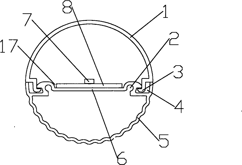
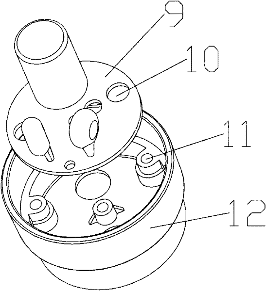
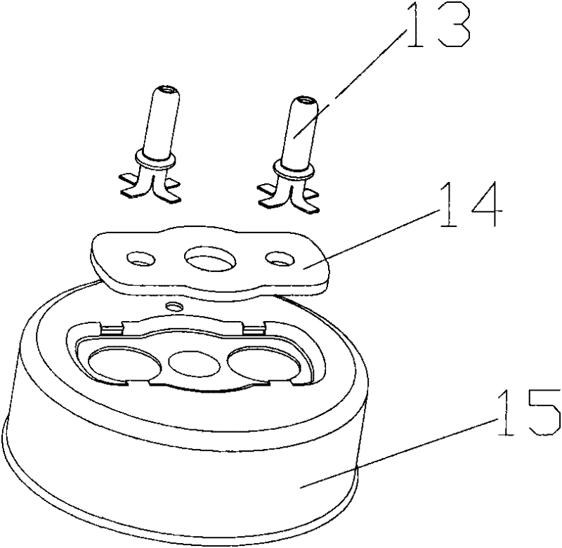
[0030] The following is attached Figure 1-5 The embodiment of the present invention is described in further detail:

[0031] 1 is the lampshade, 2 is the screw hole, 3 is the protrusion, 4 is the card slot, 5 is the heat sink, 6 is the support plate, 7 is the LED, 8 is the aluminum substrate, 9 is the power supply, 10 is the screw hole, 11 is the screw Hole, 12 is a connector, 13 is a pin, 14 is an outer reinforcement pad, 15 is a lamp holder, 16 is an inner reinforcement pad, and 17 is a limiting groove.

[0032] The present invention includes a lampshade 1, a heat sink 5, an LED 7, an aluminum substrate 8, a power supply 9, a connector 12 and a lamp cap 15. The radiator 5 is provided with a slot 4, and the position corresponding to the lampshade 1 and the slot 4 is provided with a protruding strip. 3. The shape of the raised strip 3 is matched with the slot 4, and the lampshade 1 and the radiator 5 are snapped together through the raised strip 3 and the slot 4.

[0033] T...


PUM


Abstract

The invention discloses a light-emitting diode (LED) daylight lamp, comprising a lamp shade, a radiator, an LED, an aluminum base plate, a power supply, a lamp holder and a connecting piece, wherein the lamp shade and the radiator are connected by a raised line and a clamping slot, the LED is fixed on the aluminum base plate and is arranged in a hollow cavity between the lamp shade and the radiator, the power supply is fixed in the connecting piece by a screw, and the connecting piece is arranged between the lamp holder and the radiator and is fixed with the radiator by a screw.

Description

technical field [0001] The invention relates to the technical field of lighting equipment, in particular to a light-emitting diode lighting fluorescent lamp. Background technique [0002] LED is the abbreviation of English light emitting diode (light emitting diode). LED is a semiconductor that can convert electrical energy into visible light. With many advantages such as long life, high luminous efficiency, no radiation, and low power consumption, LEDs are gradually introduced into lighting fixtures as light sources with the introduction of energy-saving and green lighting concepts. [0003] At present, incandescent bulbs or fluorescent fluorescent lamps are basically used as light sources for daily lighting such as daily bulbs and fluorescent lamps. However, the electro-optical conversion efficiency of incandescent bulbs and fluorescent fluorescent lamps is relatively low, and their heat is high Short, generally only about 3000 hours. [0004] The LED can overcome the ab...

Claims


Application Information

Patent Timeline
Patent Type & Authority Applications(China)
IPC IPC(8): F21S2/00F21V29/00F21V19/00F21K9/27F21V29/50F21Y115/10
Inventor 安国良刘欣杨士文马凤午付鹏
Owner TIANJIN JINYA ELECTRONICS
Learn More