Wet-type clutch

A wet double clutch and clutch technology, applied in the direction of clutches, friction clutches, fluid-driven clutches, etc., can solve the problems of large diameter of the rotating sealing surface of the clutch, inconvenient maintenance of the clutch, and difficulty in rotating sealing, so as to reduce processing costs, facilitate maintenance, Clutch compact effect

Active Publication Date: 2011-10-19
DONGFENG MOTOR CORP HUBEI
View PDF5 Cites 10 Cited by
  • Summary
  • Abstract
  • Description
  • Claims
  • Application Information

AI Technical Summary

Problems solved by technology

The disadvantage of the wet dual clutch with this structure is: since the rotating sealing surface of the clutch needs to cover the input shaft hole of the transmission, when the input torque of the transmission is large, the diameter of the input shaft is also relatively large, and the diameter of the rotating sealing surface of the clutch is relatively large. Rotary seals are more difficult
[0005] In addition, in the disclosed wet dual-clutch technology, the coolant of the dual-clutch is shared with the lubricating oil of the transmission, and the coolant of the dual-clutch needs to meet different requirements at the same time, which brings inconvenience to the maintenance of the clutch
[0006] In addition, most commercial vehicles do not have hydraulic systems, only pneumatic systems

Method used


Image

  • Wet-type clutch
  • Wet-type clutch
  • Wet-type clutch

Examples


Embodiment Construction

[0021] Below in conjunction with accompanying drawing and embodiment the present invention is described in further detail:

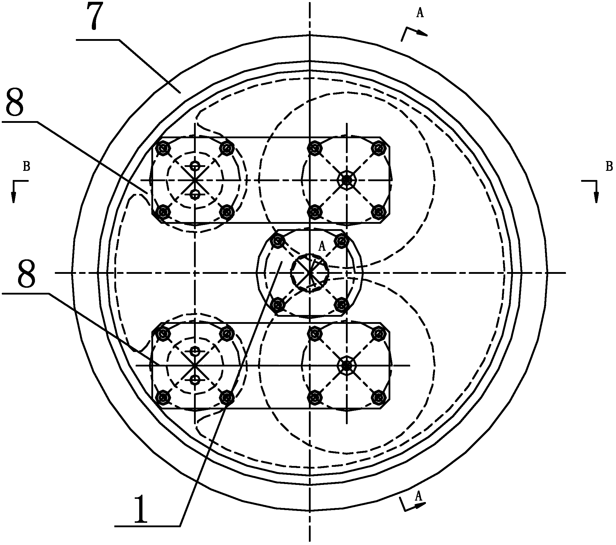
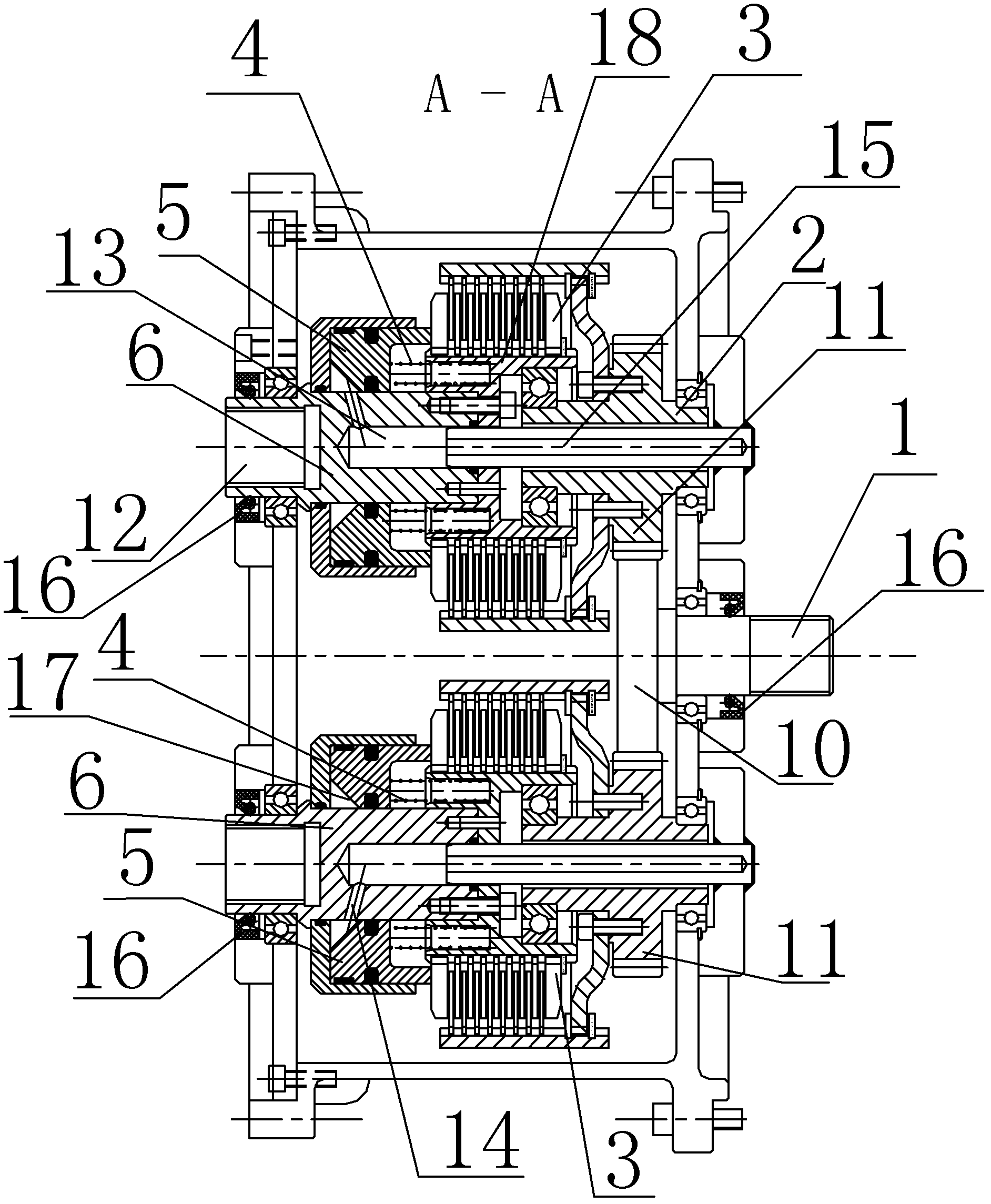
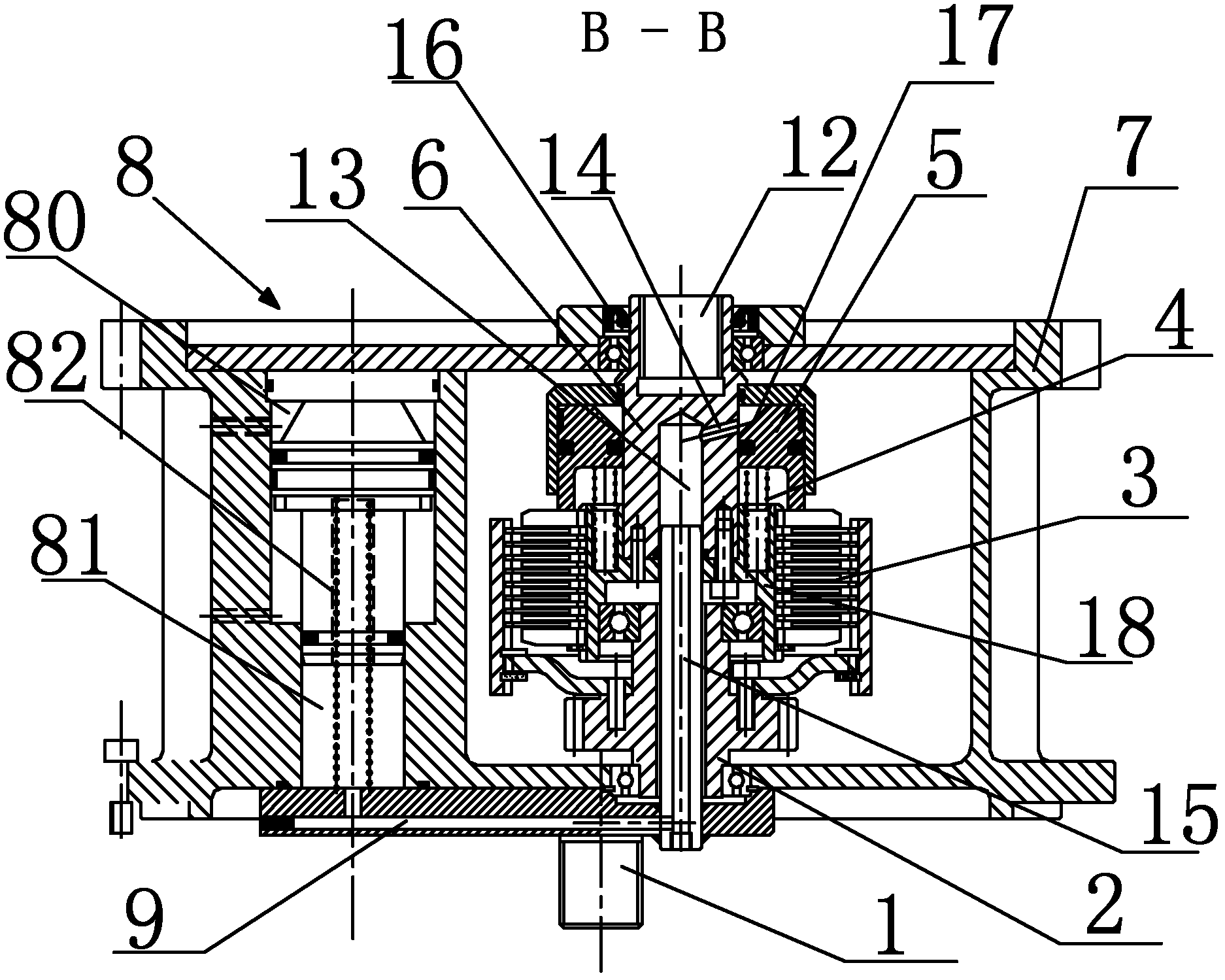
[0022] Such as Figure 1~3 A wet dual clutch shown, a wet dual clutch, includes a clutch case 7, an input shaft 1 connected to the clutch case 7 through a bearing, an input shaft gear 10 fixed on the input shaft 1, and it also includes two An output shaft assembly arranged in parallel and two gas-liquid conversion booster cylinders 8, each output shaft assembly includes a clutch driving shaft 2, a clutch driven shaft 6 coaxially arranged with the clutch driving shaft 2, fixed on the clutch The clutch 3 between the driving shaft 2 and the clutch driven shaft 6, the hydraulic cylinder 5 that drives the clutch 3, and the compression spring group 4 that separates the driving clutch 3, wherein each clutch driving shaft 2 and clutch driven shaft 6 pass through The bearing is connected with the clutch case 7, and the driving shaft gear 11 meshing with the inpu...


PUM


Abstract

The invention discloses a wet-type clutch comprising two output shaft assemblies which are arranged in parallel and two gas-liquid conversion pressure cylinders, wherein each output shaft assembly comprises a clutch driving shaft, a clutch driven shaft coaxially arranged with the clutch driving shaft, a clutch fixed between the clutch driving shaft and the clutch driven shaft, a hydraulic cylinder combined with a driving clutch, and a compression spring set driving the clutch to separate; each clutch driving shaft and each clutch driven shaft are connected with a clutch box body by bearings; each clutch driving shaft is fixed with a driving shaft gear meshed with a gear of an input shaft; a matching part, matched with an input shaft of a speed changer, is arranged at the outer end of eachdriven shaft of the clutch; and a liquid medium outlet of the gas-liquid conversion pressure cylinder is connected with a cylinder body of a hydraulic cylinder. For the wet-type clutch, the sealing effect of a hydraulic circuit is ensured, the structure is simplified, and the processing cost is reduced.

Description

technical field [0001] The invention relates to a double clutch, in particular to a wet double clutch. technical background [0002] The dual-clutch transmission enables the vehicle to automatically select and shift gears without power interruption, which not only makes the driving of the car easier, but also effectively improves the comfort, power and safety of the car. [0003] The dual clutch in the dual clutch transmission is responsible for gear shifting, start control, power transmission, torsional vibration reduction, overload protection and other important functions, and is a key component of the dual clutch transmission system. Due to the large torque capacity and easy maintenance of wet dual clutches, wet dual clutches are widely used in dual clutch transmissions. [0004] The Chinese patent authorization announcement number is CN201496426U patent discloses a kind of wet type double clutch, and this wet type double clutch comprises the inner clutch and the outer c...

Claims


Application Information

Patent Timeline
IPC IPC(8): F16D21/02F16D25/0638F16D13/58F16D13/72F16D25/12F16C3/02
Inventor 蒋鸣张成海余建华魏为民
Owner DONGFENG MOTOR CORP HUBEI
Why Eureka
Try Eureka