
Apparatus for determining concentration of gaseous component

A technology for concentration measurement and gas composition, which is applied in the field of gas composition concentration measurement devices, and can solve the problem of high price of photodetectors

Inactive Publication Date: 2011-10-12
IHI CORP
View PDF12 Cites 3 Cited by
  • Summary
  • Abstract
  • Description
  • Claims
  • Application Information

AI Technical Summary

Problems solved by technology

Therefore, a photodetector capable of detecting a large range of intensities is required, so the price of the photodetector is high.

Method used


Image

  • Apparatus for determining concentration of gaseous component
  • Apparatus for determining concentration of gaseous component
  • Apparatus for determining concentration of gaseous component

Examples


no. 1 approach

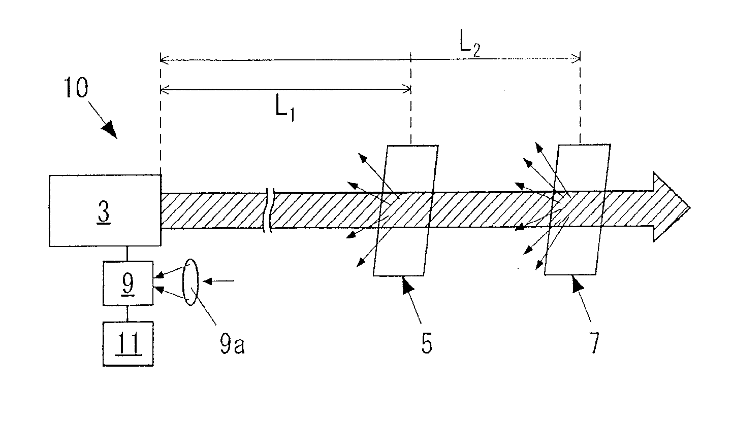
[0031] figure 1 It is a configuration diagram of the gas component concentration measuring device 10 according to the first embodiment of the present invention. This gas component concentration measuring device 10 is a device that emits a laser beam into a gas, and detects the concentration of a target component in the gas based on the laser beam passing through the gas. The target components are, for example, carbon dioxide, ammonia, methane, sulfur dioxide gas (SO 2 ) and other sulfide gases (SO x ) or nitrogen oxide gas (NO) such as nitric oxide (NO) x ).

[0032] The gas component concentration measurement device 10 has a laser emitting device 3 , first and second scatterers 5 and 7 , a photodetector 9 , and a concentration calculation device 11 .

[0033] The emission wavelength of the laser emitting device 3 is the light absorption wavelength λ of the target component 1 The wavelength of the first laser beam is the non-absorbing wavelength λ of the object component ...

no. 2 approach

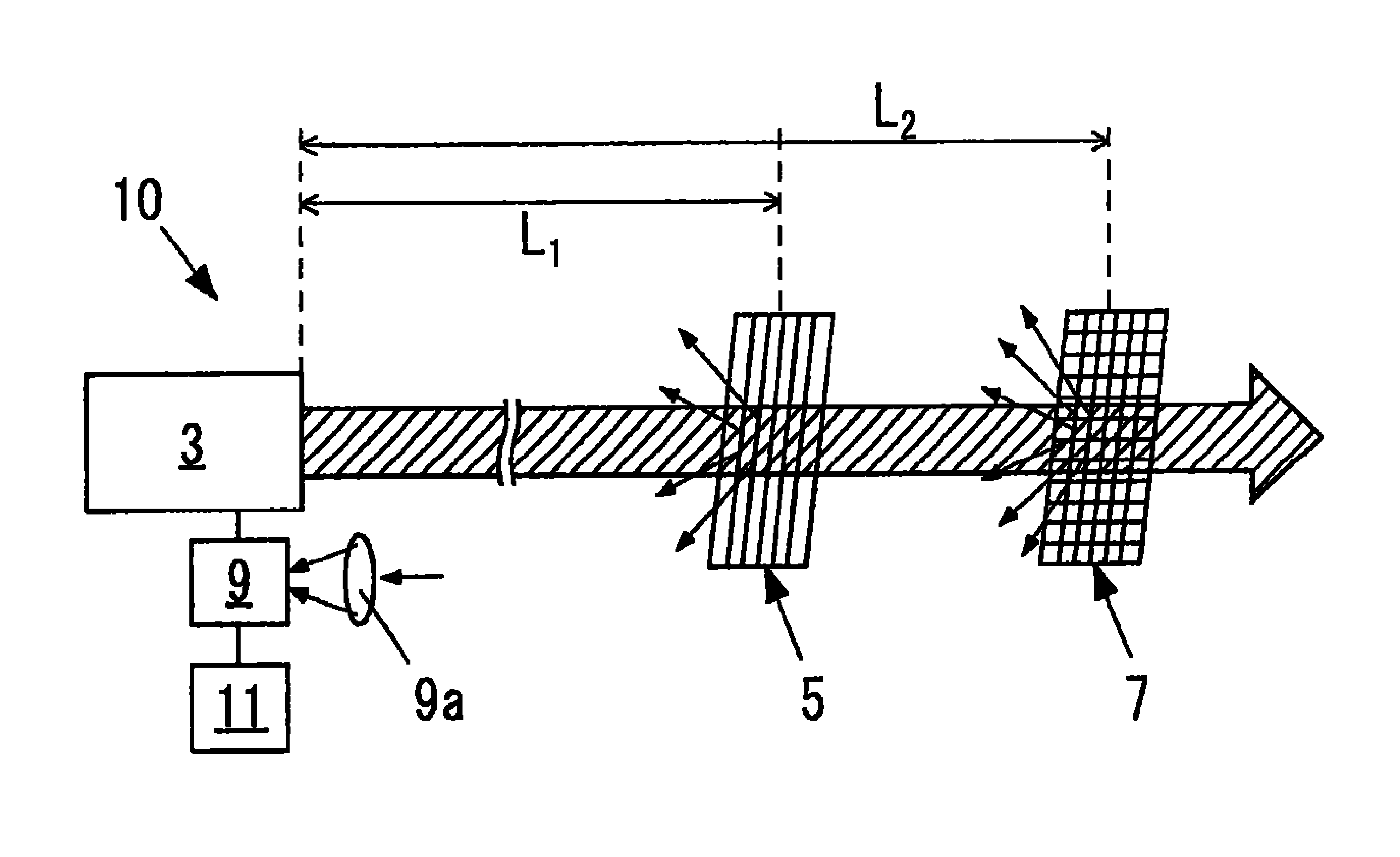
[0073] image 3 It is a configuration diagram of a gas component concentration measuring device 10 according to a second embodiment of the present invention.

[0074] As shown in the figure, the first and second scatterers 5 and 7 are scatterers formed by intentionally adding damage, dirt, built-in objects, or a combination thereof to the glass. Other structures in the second embodiment are the same as those in the first embodiment.

[0075] In addition, in the second embodiment, in order to make the second scatterer 7 scatter the laser beam more than the first scatterer 5, the degree and density of the damage, dirt, and inclusions added to the glass 7 are higher than those added to the glass 7. The degree and density of damage, dirt, and built-in objects on the glass 5 .

no. 3 approach

[0077] Figure 4 It is a configuration diagram of a gas component concentration measuring device 10 according to a third embodiment of the present invention.

[0078] As shown in the figure, the first and second scatterers 5 and 7 are spherical members attached to the tip of a pole. Other structures in the third embodiment are the same as those in the first embodiment.

[0079] In addition, in the third embodiment, in order to make the second scatterer 7 scatter the laser beam more than the first scatterer 5, the Figure 4 In this case, the number of spherical members constituting the second scatterer 7 is greater than the number of spherical members constituting the first scatterer 5 .

[0080] [Gas Component Concentration Measurement System]

[0081] Figure 5 It is a configuration diagram of a gas component concentration measurement system 20 using the gas component concentration measurement device 10 described above. The gas component concentration measurement system ...


PUM


Abstract

An apparatus for determining the concentration of a gaseous component is provided with which a sufficiently large optical values are detected without the need of using a laser having a high emission intensity or a large light collector, and the determination of the concentration of a target component within a desired section is rendered possible. The apparatus comprises: a laser (3) which emits a first laser light having such a wavelength that the target component absorbs the light and a second laser light having such a wavelength that the target component does not absorb the light; first and second scattering objects (5) and (7) located in the range irradiated with the first laser light and the second laser light and disposed apart from each other in the direction of the emission of the first laser light and second laser light; a photodetector (9) which detects first and second scattered lights resulting from the scattering of the first laser light and second laser light by the first scattering object (5) and third and fourth scattered lights resulting from the scattering of the first laser light and second laser light by the second scattering object (7); and a concentration calculator (11) which calculates the concentration of the target component in the section ranging from the first scattering object (5) to the second scattering object (7), based on the values detected by the photodetector (9).

Description

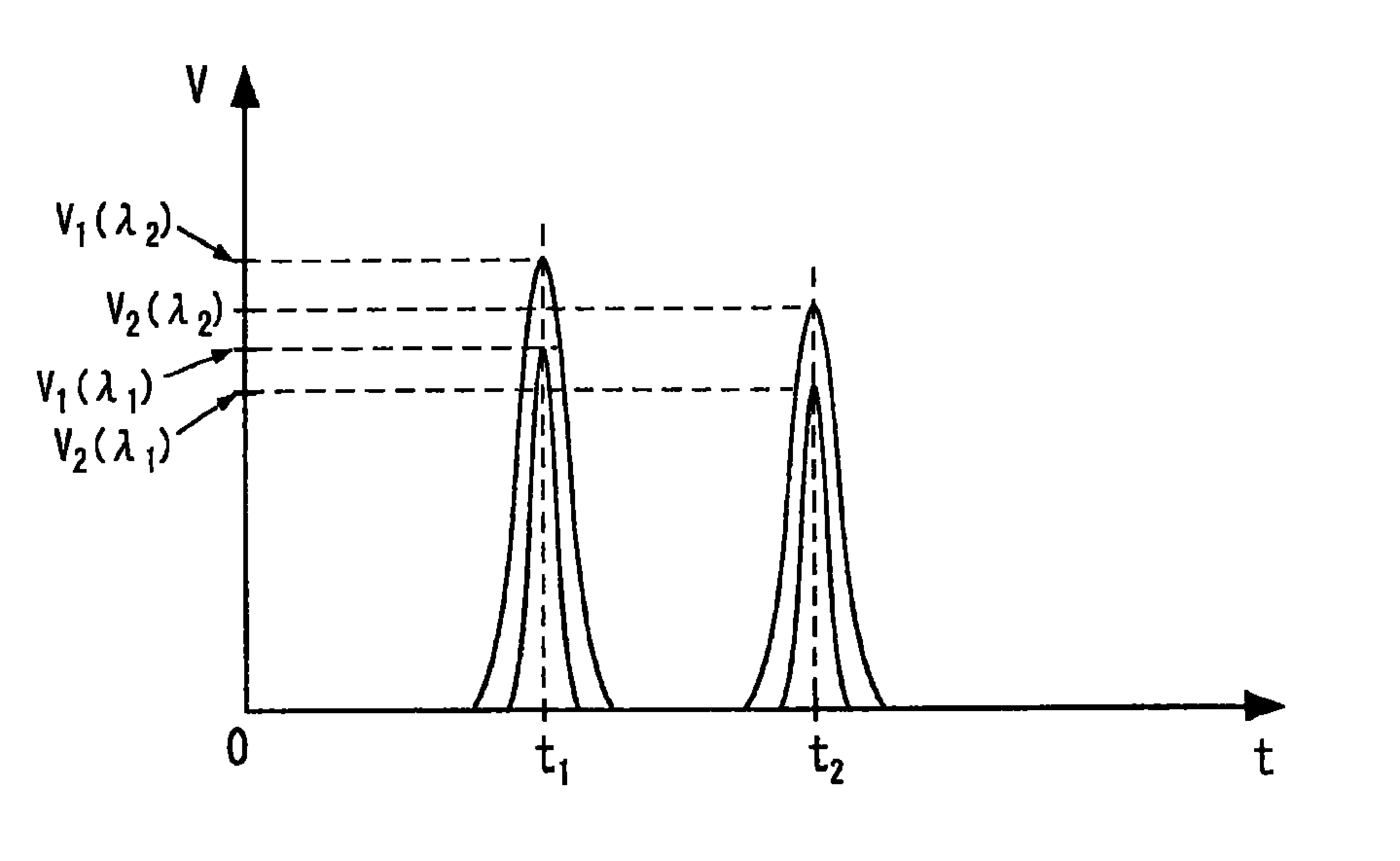
technical field [0001] The present invention relates to a gas component concentration measuring device for measuring the concentration of a target component in gas using a laser beam. Background technique [0002] The concentration of the specific target component contained in the gas can be measured by the following method. [0003] The gas emitted from the laser emitting device has an absorption wavelength λ unique to the target component 1 laser. Absorption wavelength λ is detected by a photodetector installed near the laser irradiation device 1 The laser beam is scattered light after being scattered by dust in the gas or the gas itself. In this case, a difference occurs in the timing of detection of scattered light by the photodetector depending on the distance between the laser emitting device and the scattering position of the laser beam. By converting this time characteristic into a distance characteristic, a detection signal of scattered light from a desired sect...

Claims


Application Information

Patent Timeline
Patent Type & Authority Applications(China)
IPC IPC(8): G01N21/27G01N21/47
CPCG01N21/3504G01N2021/1793G01N2021/3513G01N2021/392G01N21/39G01N9/24
Inventor 伊泽淳滨野靖德久保田伸彦
Owner IHI CORP
Learn More