


Quick Research
Generate reliable direction feasibility study reports for your R&D in just a few steps.

Technical Q&A
Discover and master advanced knowledge NOW. Basics, ideas, possibilities, all at once.

Find Solutions
As an expert in R&D theories, this can generate solutions to your technical problems instantly.

Evaluate Feasibility
Analyze your overall solution with one click, know your potential R&D risks in advance.

Monitor Landscape
Get weekly tech updates, stay abreast of the latest tech innovations and key insights.
Blood vessel display device
A technology for display devices and blood vessels, which is applied in medical science, sensors, diagnostic recording/measurement, etc., and can solve problems such as focus shift, image blur, and inability to display clear blood vessel images in living tissue.
- Summary
- Abstract
- Description
- Claims
- Application Information
AI Technical Summary
Problems solved by technology
Method used
Image

Examples
no. 1 Embodiment approach
[0038] First, a first embodiment of the blood vessel display device of the present invention will be described.
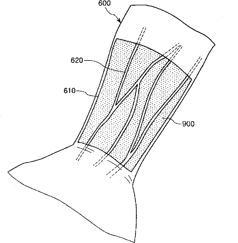
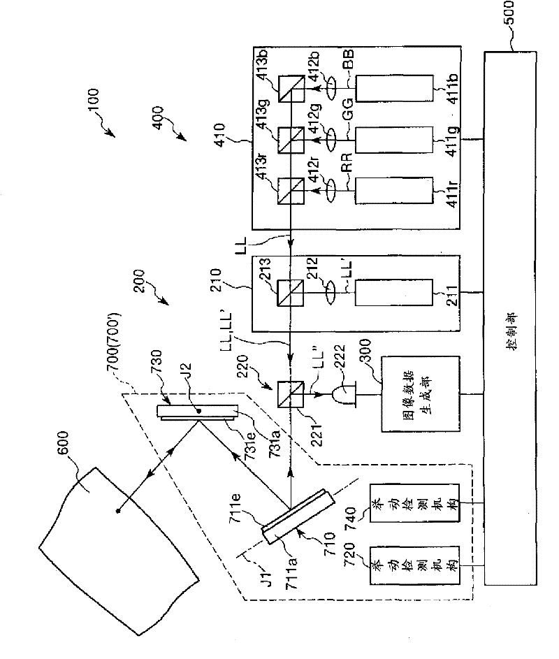
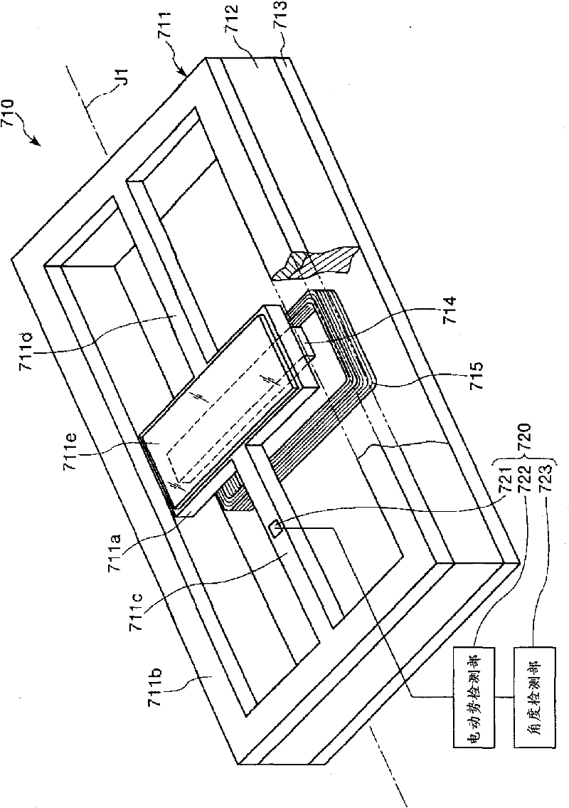
[0039] figure 1 is a diagram showing an image displayed by the blood vessel display device of the present invention, figure 2 is a schematic diagram of the blood vessel display device of the present invention, image 3 yes figure 2 A partially cutaway perspective view of an optical scanner included in the blood vessel display device shown, Figure 4 is true image 3 The drive of the optical scanner is shown in the cross-sectional view for illustration. Among them, for the convenience of explanation, the image 3 , Figure 4 The upper side is called "upper", the lower side is called "lower", the left side is called "left", and the right side is called "right".
[0040] The blood vessel display device 100 is a device for visualizing blood vessels (in particular, veins) existing on the surface of living tissue. Such blood vessel display device 100 is, for ex...
no. 2 Embodiment approach
[0106] Next, a second embodiment of the blood vessel display device of the present invention will be described.
[0107] Figure 5 is a schematic diagram of a blood vessel display device according to a second embodiment of the present invention, Image 6 is expressed by Figure 5 A diagram showing an example of an image displayed by the display mechanism.
[0108] Hereinafter, the blood vessel display device 100A of the second embodiment will be described focusing on differences from the blood vessel display device 100 of the first embodiment described above, and the description of the same matters will be omitted.
[0109] The blood vessel display device 100A of the second embodiment has a point determination unit 800 , and is substantially the same as the blood vessel display device of the first embodiment described above except that the image displayed on the irradiated site 610 is different. In addition, the same code|symbol is attached|subjected to the same structure a...
PUM
 Abstract
Description
Claims
Application Information
 - R&D Engineer
- R&D Manager
- IP Professional
- Industry Leading Data Capabilities
- Powerful AI technology
- Patent DNA Extraction
Browse by: Latest US Patents, China's latest patents, Technical Efficacy Thesaurus, Application Domain, Technology Topic, Popular Technical Reports.
© 2024 PatSnap. All rights reserved.Legal|Privacy policy|Modern Slavery Act Transparency Statement|Sitemap|About US| Contact US: help@patsnap.com