
Piston cylinder assembly

A piston cylinder and assembly technology, which is applied in the direction of fluid pressure actuation device, etc., can solve the problems of heavy weight of multi-stage piston cylinders, troubles for users, and breakage, so as to avoid damage and breakage of drill pipes and ensure stable and normal work , The effect of reducing the installation space

Inactive Publication Date: 2011-10-05
HEFEI AEROSPACE HYDRAULIC MACHINERY
View PDF7 Cites 3 Cited by
  • Summary
  • Abstract
  • Description
  • Claims
  • Application Information

AI Technical Summary

Problems solved by technology

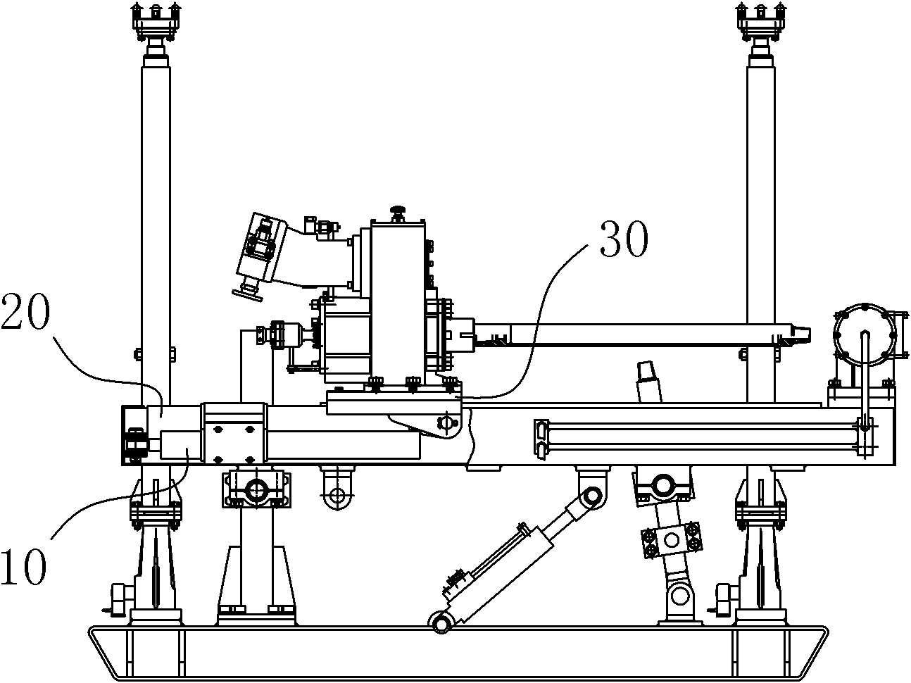
The above-mentioned mechanism often has the following defects in use: First, the strokes of the multi-stage piston cylinders are all realized by socketing and reciprocating expansion and contraction of the rod bodies of each level. Some of the rods are used to connect with each other, so that the actual stroke is smaller than the total length of the rods at all levels, thereby reducing its actual use efficiency; secondly, the overall weight of the multi-stage piston cylinder is large and the mechanism is complicated, and the installation and maintenance are cumbersome and costly. Finally, because the multi-stage piston cylinders are mostly made of rods at all levels according to the diameter from thick to thin or from thin to thick, and tunnel drilling rigs are mostly used in environments with heavy loads and high impacts, often due to multiple The power of the piston cylinder rod body is not uniform, so that the drill pipe of the drilling rig cannot get a constant thrust, and eventually it is damaged or even broken, which not only increases the maintenance cost, but also causes great troubles to the users.
Therefore, its inherent stroke is twice that of the ordinary oil cylinder (that is, single-stage double-acting piston cylinder). However, the above-mentioned solution still has the problem of uneven application of force due to the asymmetric arrangement of the two cylinders. When this technical solution is applied to the above-mentioned tunnel drilling rig, it will inevitably lead to the fact that the drill rod of the drilling rig cannot get a constant thrust or pulling force due to uneven force, which will eventually cause it to be damaged or even broken.

Method used


Image

  • Piston cylinder assembly
  • Piston cylinder assembly
  • Piston cylinder assembly

Examples


Embodiment Construction

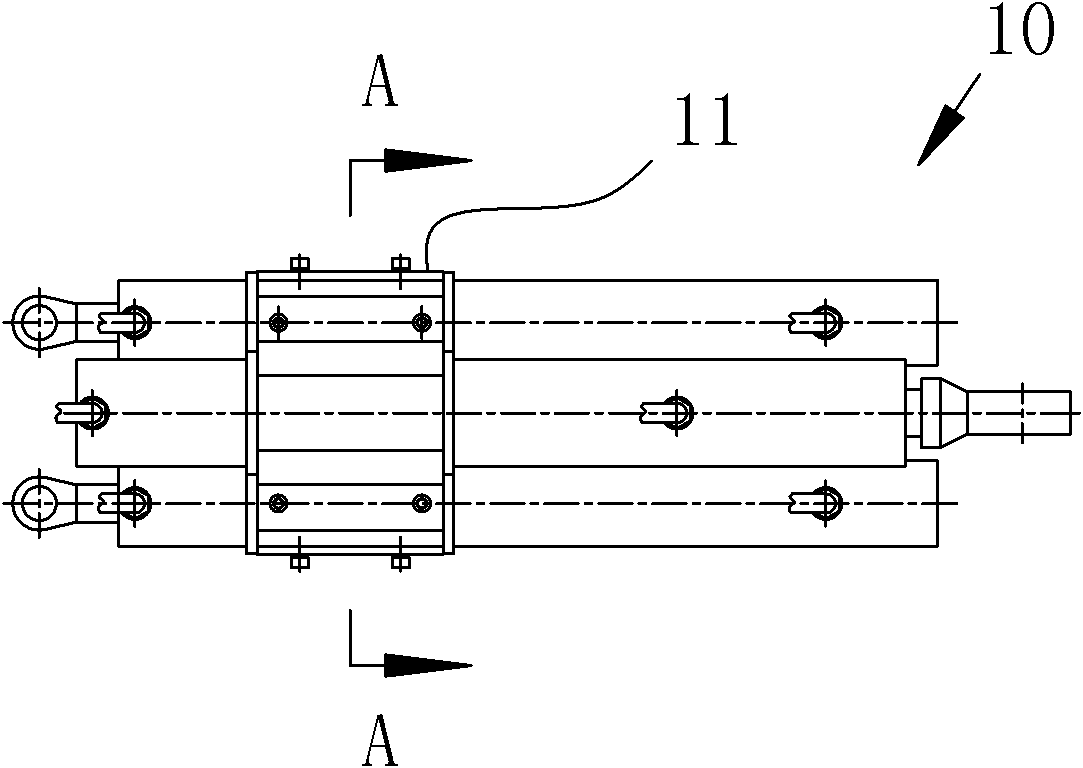
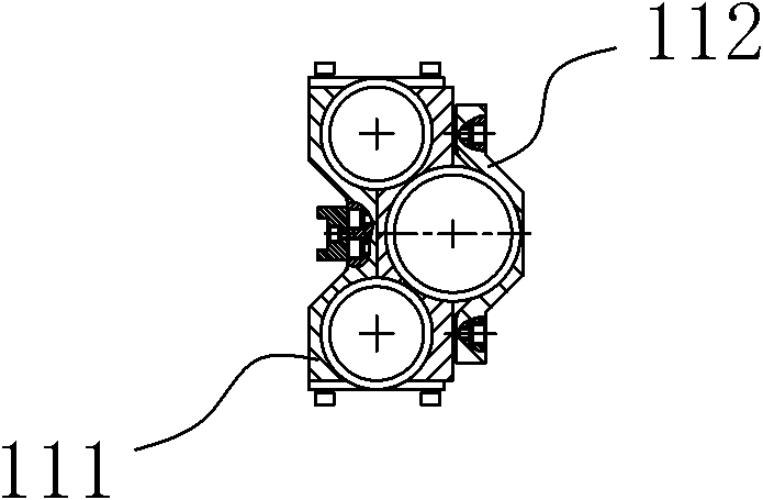
[0014] A piston-cylinder assembly, including a piston-cylinder unit 10, the piston-cylinder unit 10 is composed of three or more piston-cylinders in reverse and fixedly connected to each other, and the piston-cylinder units 10 are reversed to form The pushing or pulling forces are arranged symmetrically.

[0015] In the present invention, since the cylinder bodies of each layer of piston cylinders are fixed to each other and move in reverse, the stroke loss of the piston rod body itself is reduced, making its stroke larger than that of a single multi-stage piston cylinder, thereby making it Under the same stroke, the volume is smaller and the installation space is reduced. At the same time, the present invention can ensure uniform force application by reducing the number of stages of a single piston cylinder under the same stroke. At the same time, because the piston-cylinder units 10 are opposite to each other And the thrust or pulling force that forms are all symmetrically a...


PUM


Abstract

The invention belongs to the field of mining machines, and in particular relates to a piston cylinder assembly for a mining tunnel drilling machine. The piston cylinder assembly comprises more than three piston cylinder units, wherein piston cylinders are combined reversely, and cylinder bodies of the piston cylinders are fixedly connected with one another. Push forces or pull forces formed by the reversely arranged piston cylinder units are symmetrically arranged, so that the piston cylinder assembly applies forces uniformly, is operated stably, and can ensure the normal and stable operation of the drilling machine.

Description

technical field [0001] The invention belongs to the field of mining machinery, and in particular relates to a piston-cylinder assembly for a mining tunnel drilling machine. Background technique [0002] Tunnel drilling rig is a drilling rig specially used for drilling in underground tunnels. It is mainly used for deep geological exploration, gas drainage, water injection, ventilation and other projects in tunnels. Its working mode is mostly to drive the multi-stage piston cylinder through pneumatic, hydraulic, etc. to realize the reciprocating movement of the drilling rig body and the drill pipe on the frame, and finally realize the drilling and return functions of the drilling rig. The above-mentioned mechanism often has the following defects in use: First, the strokes of the multi-stage piston cylinders are all realized by socketing and reciprocating expansion and contraction of the rod bodies of each level. Some of the rods are used to connect with each other, so that th...

Claims


Application Information

Patent Timeline
Patent Type & Authority Applications(China)
IPC IPC(8): F15B15/00
Inventor 张孟和苏芳冰梁继成
Owner HEFEI AEROSPACE HYDRAULIC MACHINERY
Learn More