Radio communication device
A technology of a wireless communication device and a communication circuit is applied in the field of RFID tags to achieve the effect of realizing broadband
- Summary
- Abstract
- Description
- Claims
- Application Information
AI Technical Summary
Problems solved by technology
Method used
Image

Examples
Embodiment 1
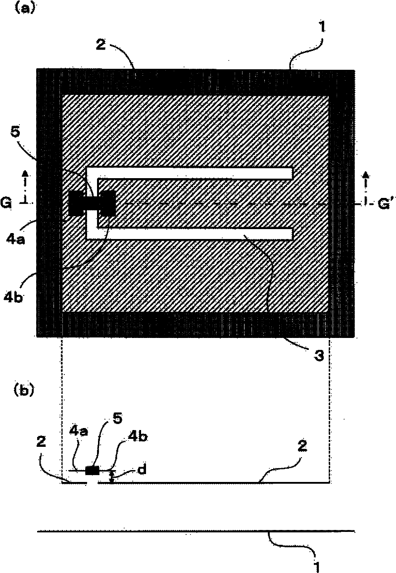
[0036] figure 1 These are a plan view and a cross-sectional view showing the wireless communication device of the first embodiment of the present invention, and show the structure of an RFID tag that functions as a wireless communication device.
[0037] figure 1 (A) is a top view, figure 1 (B) is along figure 1 The cross-sectional view of the G-G' line in (a).
[0038] in figure 1 Here, the RFID tag includes a ground conductor 1, a radiation conductor (hereinafter referred to as “conductor”) 2, a slot line (hereinafter referred to as “slot”) 3, capacitive coupling units 4a, 4b, and an IC chip 5.
[0039] The ground conductor 1 is a conductor composed of a finite size, such as figure 1 (A) shows a rectangular shape. The conductor 2 is a plate-shaped conductor, and has a rectangular shape, for example, like the ground conductor 1.
[0040] The conductor 2 is arranged substantially parallel to the ground conductor 1 with an interval therebetween, and forms a microstrip antenna together ...
Embodiment 2
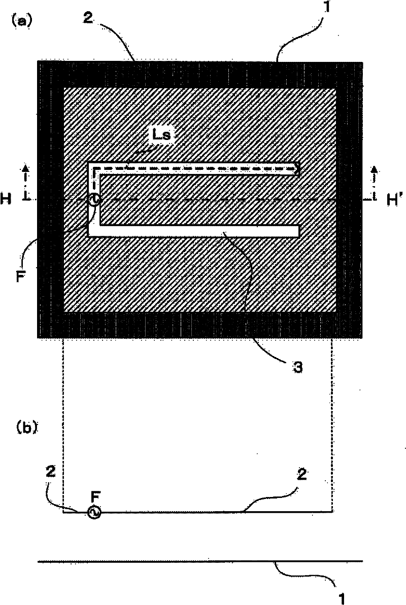
[0109] In addition, in the example 1 ( figure 1 ), let the shape of the slot 3 of the conductor 2 be arbitrary, but as Picture 12 As shown, by using the slot 3A of the designed shape, the coupling degree of the microstrip antenna composed of the ground conductor 1 and the conductor 2 and the slot 3A can be adjusted, and the degree of freedom of design can be improved.
[0110] Picture 12 It is a plan view showing the RFID tag constituting the wireless communication device of the second embodiment of the present invention. For the same configuration as described above, the same reference numerals as described above are attached, and detailed descriptions are omitted.
[0111] in Picture 12 In the above-mentioned embodiment 1, the difference from the above-mentioned embodiment 1 is that a folded back slot portion is formed in two places (at least one place) of the slot 3A to generate an internal magnetic field with respect to the microstrip antenna composed of the ground conductor 1...
Embodiment 3
[0128] In addition, in the examples 1, 2 ( figure 1 , Picture 12 In ), for the slot 3 of the conductor 2, capacitive coupling units 4a, 4b are formed by a laminated structure, but it can also be as Figure 15 In that way, the capacitive coupling units 4a, 4b are formed on the same plane as the slot 3B.
[0129] Figure 15 It is a plan view showing the RFID tag constituting the wireless communication device of the third embodiment of the present invention. figure 1 ) For the same parts, the same symbols as those described above are attached, and detailed descriptions are omitted.
[0130] in Figure 15 Among them, the difference from the first and second embodiments is that the capacitive coupling units 4A and 4B are arranged on the same plane as the slot 3B.
[0131] In this case, the capacitive coupling units 4A and 4B are each composed of a third conductor, the capacitive coupling unit 4A is arranged close to one side of the slot 3B, and the capacitive coupling unit 4B is arranged ...
PUM
 Abstract
Description
Claims
Application Information
 - Generate Ideas
- Intellectual Property
- Life Sciences
- Materials
- Tech Scout
- Unparalleled Data Quality
- Higher Quality Content
- 60% Fewer Hallucinations
Browse by: Latest US Patents, China's latest patents, Technical Efficacy Thesaurus, Application Domain, Technology Topic, Popular Technical Reports.
© 2025 PatSnap. All rights reserved.Legal|Privacy policy|Modern Slavery Act Transparency Statement|Sitemap|About US| Contact US: help@patsnap.com