Illuminating device and display device

A lighting device and light guide plate technology, applied in lighting devices, lighting and heating equipment, instruments, etc., can solve the problems of display quality degradation, uneven brightness distribution, uneven display of liquid crystal display devices, etc., and achieve the goal of preventing the decline of display quality Effect

Inactive Publication Date: 2011-09-28
SHARP KK
View PDF1 Cites 6 Cited by
  • Summary
  • Abstract
  • Description
  • Claims
  • Application Information

AI Technical Summary

Problems solved by technology

As a result, such as Figure 8 As shown in B, the light guide plate 104 is deformed into a wavy shape, thereby causing non-uniform brightness distribution in the lighting device, causing display unevenness in the liquid crystal display device and degrading the display quality.
The larger the screen size, the more pronounced the problem

Method used


Image

  • Illuminating device and display device
  • Illuminating device and display device
  • Illuminating device and display device

Examples


Embodiment approach 1

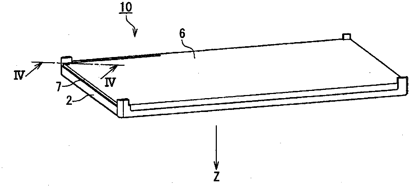
[0036] figure 1 It is an exploded perspective view showing a schematic configuration of the liquid crystal display device 1 according to Embodiment 1 of the present invention. For the convenience of the following description, the thickness direction of the liquid crystal display device 1 ( figure 1 The axis parallel to the up and down direction on the paper is taken as the Z axis. The direction of the arrow of the Z-axis indicates the viewing side of the liquid crystal display device 1 .

[0037] This liquid crystal display device 1 includes: a transmissive liquid crystal panel 8 as a display unit;

[0038] The illuminating device 10 includes a resin frame 2 , at least one optical sheet 3 , a light guide plate 4 , a reflection sheet 5 , and a back plate 6 in order from the liquid crystal panel 8 side along the Z axis. The lighting device further includes a light source 7 .

[0039] Light source 7 generates illumination light for illuminating liquid crystal panel 8 . For...

Embodiment approach 2

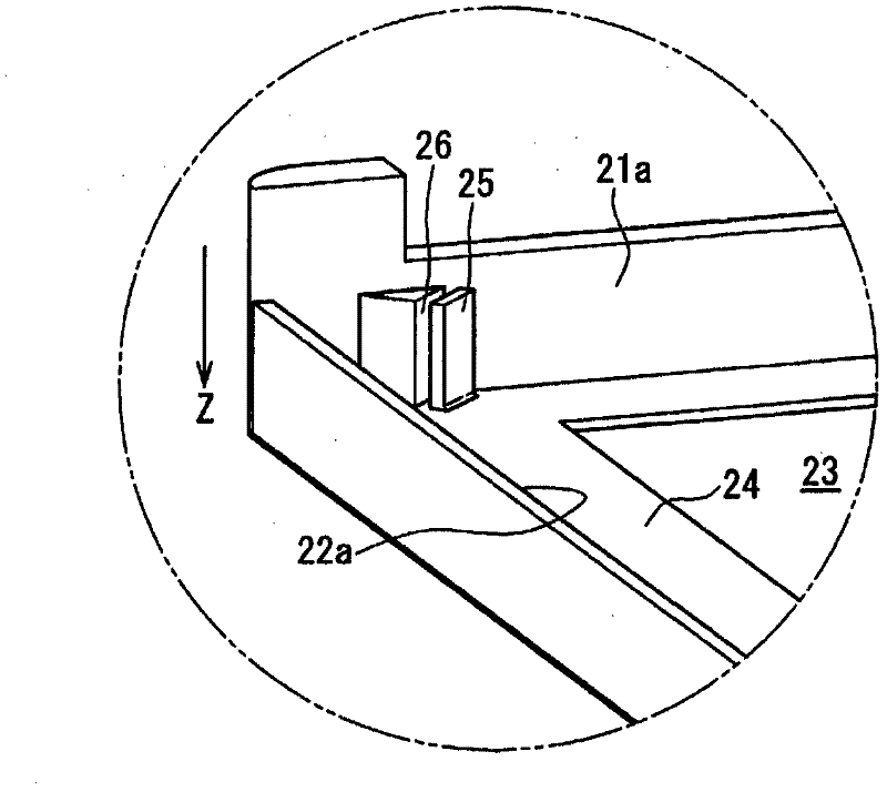
[0064] Figure 7 It is a partially enlarged cross-sectional view of the lighting device 10a according to Embodiment 2 of the present invention along a plane parallel to the thickness direction. In Embodiment 2, the inclined surface 45 a is formed on the contact surface 45 of the light guide plate 4 that faces the protrusion 25 . Other than that, it is the same as Embodiment 1, and the same reference numerals are attached to the same constituent elements as Embodiment 1, and description thereof will be omitted.

[0065] The inclined surface 45 a is inclined so as to recede as it gets closer to the emission surface 43 in the thickness direction (Z-axis direction) of the light guide plate 4 (that is, to move away from the protrusion 25 ). The inclined surface 45 a is adjacent to the emission surface 43 . By forming such an inclined surface 45 a on the contact surface 45 , when the protrusion 25 is inclined due to the force F received from the light guide plate 4 due to the elon...


PUM


Abstract

On the side of a light outgoing surface (43) of a light guide plate (4), a resin frame (2) is arranged with at least one optical sheet (3) therebetween. A protruding section (25) facing an end surface (45) adjacent to the light outgoing surface of the light guide plate is arranged on the resin frame. The protruding section is elastically deformable to the side opposite to the light guide plate which the protruding section faces. Since the protruding section elastically deforms and absorbs the stretch quantity of the light guide plate, the light guide plate does not deform. Therefore, light guide plate deformation generated due to relative dimensional change of the light guide plate due to changes of temperature and humidity can be eliminated over a long period of time.

Description

technical field [0001] The present invention relates to a lighting device, particularly a lighting device provided with a light guide plate. In addition, the present invention relates to a display device including such a lighting device. Background technique [0002] In recent years, liquid crystal display devices have been widely used in televisions, monitors, mobile phones, and the like because they are thinner and lighter than conventional Braun tubes. Such a liquid crystal display device includes: an illumination device (backlight device) that emits illumination light; and a liquid crystal panel that displays a desired image by functioning as a shutter for the illumination light from the illumination device. [0003] The aforementioned lighting devices are roughly classified into direct type and edge type according to the arrangement of the light source with respect to the liquid crystal panel. The edge-light type is easier to achieve thinner than the direct-type type,...

Claims


Application Information

Patent Timeline
Patent Type & Authority Applications(China)
IPC IPC(8): F21S2/00G02F1/13357F21Y101/02F21Y103/00F21Y105/00
CPCG02F1/133615G02B6/0088G02F2001/133314G02F2201/54G02F1/133314
Inventor 矶部宏晶下条一哉
Owner SHARP KK
Why Eureka
Try Eureka