Eureka AIR delivers breakthrough ideas for toughest innovation challenges, trusted by R&D personnel around the world.

Handle shaft assemblies for bottom loading couplers

A handle shaft and coupling technology, applied in couplings, valve devices, transportation and packaging, etc., can solve problems such as affecting the operation of the bottom loading coupling, damage to the bottom loading coupling, difficulties, etc.

Inactive Publication Date: 2011-09-28
DELAWARE CAPITAL FORMATION INC
View PDF3 Cites 2 Cited by
  • Summary
  • Abstract
  • Description
  • Claims
  • Application Information

AI Technical Summary

Problems solved by technology

Getting the pin out of the hole can be a difficult operation requiring removal of the bottom loading linkage from the loading arm assembly
Furthermore, having the pin clear of the hole may damage the body and / or hole of the bottom loading coupling, thereby adversely affecting the operation of the bottom loading coupling

Method used


Image

  • Handle shaft assemblies for bottom loading couplers
  • Handle shaft assemblies for bottom loading couplers
  • Handle shaft assemblies for bottom loading couplers

Examples


Embodiment Construction

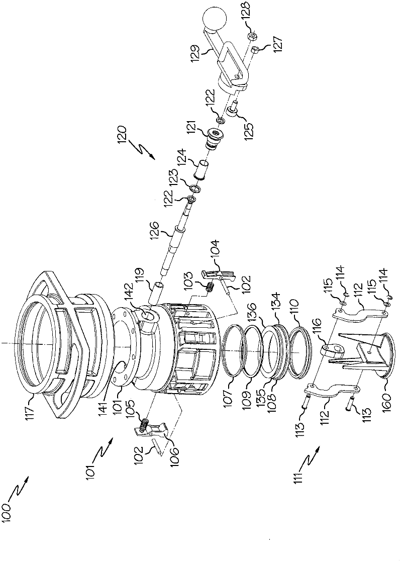
[0021] figure 1 An exploded view of the bottom loading coupling is shown generally. The bottom loading coupling generally includes a body having a poppet valve assembly disposed therein. The poppet valve assembly is actuated by the handle shaft assembly which includes a tube spacer, handle shaft, stuffing box, sleeve bearings, cam followers, and operating handle. The bottom loading coupling, handle shaft assembly and stuffing box will be described in more detail herein with specific reference to the accompanying drawings.

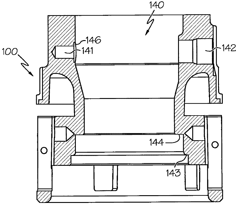
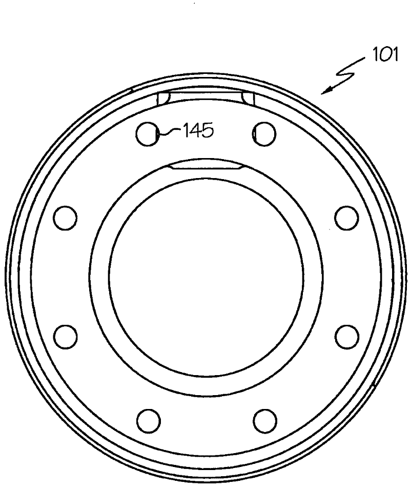
[0022] refer to figure 1 , an exploded view of one embodiment of a bottom loading coupling 100 is shown. The bottom loading coupling 100 generally includes a coupling body 101 having a poppet valve assembly 111 disposed within a cylindrical cavity formed by the body 101 . Although the exemplary body 101 shown in the figures is substantially cylindrical, it should be understood that the body 101 may have other shapes and configurations. Outer coupling s...


PUM


Abstract

A handle shaft assembly includes a tube spacer, a handle shaft, a stuff box, and an operational handle. The stuff box may be configured for insertion into a through-hole within a bottom loading coupler body and include first and second stuff box ends defining a cylindrical cavity. A first sealing member may be positioned on the first stuff box end, and a second sealing member positioned on the second stuff box end. The tube spacer may be configured to be positioned within a blind counterbore of the bottom loading coupler body. The handle shaft may include a first end positioned within the tube spacer configured to be positioned with a blind bore of the bottom loading coupler body, a linkage section configured to be coupled to a drive linkage of a poppet valve assembly, and a second end extending through the cylindrical cavity of the stuff box. The operational handle is mechanically coupled to the second end of the handle shaft.

Description

technical field [0001] Embodiments of the present invention relate generally to bottom loading couplings and, more particularly, to handle shaft assemblies for bottom loading couplings. Background technique [0002] Transferring liquid products from larger volume storage tanks to tank trucks or railcars involves moving liquid products through fixed piping risers to storage of various sizes and orientations located on or in tank trucks or railcars container. Various configurations of tank cars or railcars may require flexible fluid transfer systems such as loading arm assemblies. The loading arm assembly is part of a pipeline capable of handling high flows and line pressures, which can be moved vertically and horizontally to accommodate transport vehicles of various configurations. [0003] One particular method of transferring liquid product through a loading arm is to use a bottom loading coupling to couple the loading arm to the storage container of the transport vehicle...

Claims


Application Information

Patent Timeline
Patent Type & Authority Applications(China)
IPC IPC(8): F16K31/524F16L37/084F16L37/44
CPCF16K31/52408Y10T74/20732Y10T137/87973
Inventor M·J·塔施J·P·罗斯
Owner DELAWARE CAPITAL FORMATION INC
Why Eureka
Eureka Blog
Learn More