
Machine tool with an electrical generator for passive power generation

A technology for machine tools and generators, which is used in manufacturing tools, synchronous motors with static armatures and rotating magnets, synchronous machines, etc., and can solve problems such as the problem of power supply for light-emitting devices

Active Publication Date: 2011-09-28
ROBERT BOSCH GMBH
View PDF5 Cites 3 Cited by
  • Summary
  • Abstract
  • Description
  • Claims
  • Application Information

AI Technical Summary

Problems solved by technology

[0002] For example DE 10 2006 045157 A1 discloses a tool in which a light emitting device is integrated, but supplying power to the light emitting device is a problem

Method used


Image

  • Machine tool with an electrical generator for passive power generation
  • Machine tool with an electrical generator for passive power generation
  • Machine tool with an electrical generator for passive power generation

Examples


Embodiment Construction

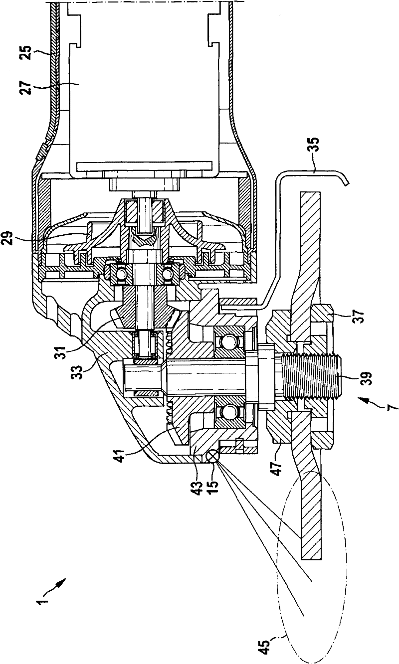
[0029] figure 1 The machine tool shown in ~ 7 is an embodiment of an angle grinder equipped with a rotating rotor, Figure 8-1 0 shows an embodiment of a wire saw equipped with a linear reciprocating rotor.

[0030] figure 1 A schematic cross-sectional view of the angle grinder 1 is shown. Angle grinder 1 has such as motor housing 25, motor 27, fan 29, pinion 31, transmission mechanism housing 33, protective cover 35, double hole nut 37, main shaft 39, crown gear 41, bearing flange 43 and installation Common parts like flange 47. The light source 15 can illuminate the work area 45 or the work surface 45 . For example, the light source 15 can be integrated on the bearing flange 43 . As rotor 7 of angle grinder 1 , eg crown gear 41 , mounting flange 47 or spindle 39 can be used.

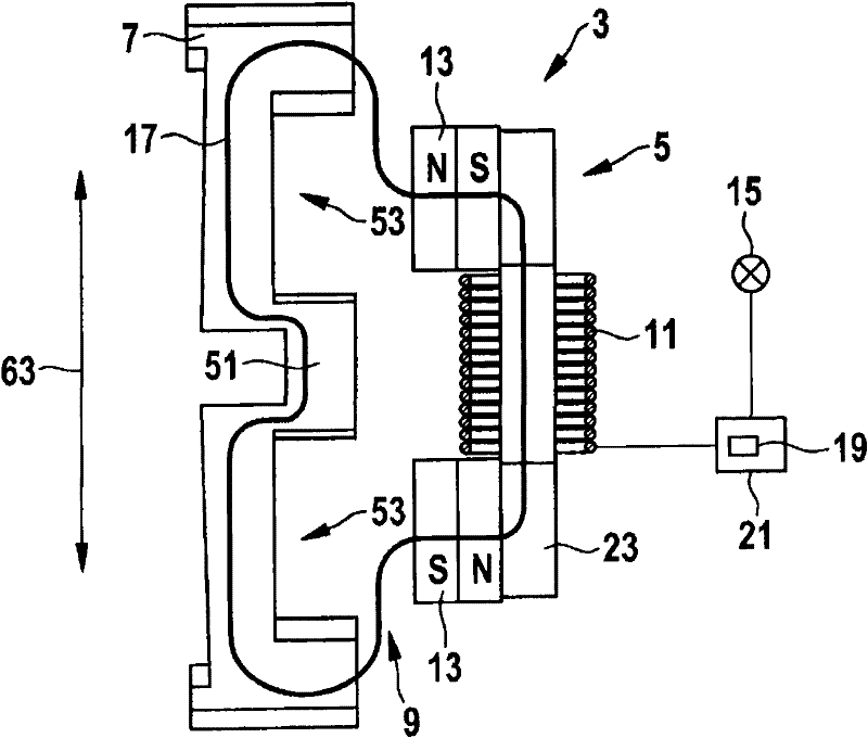
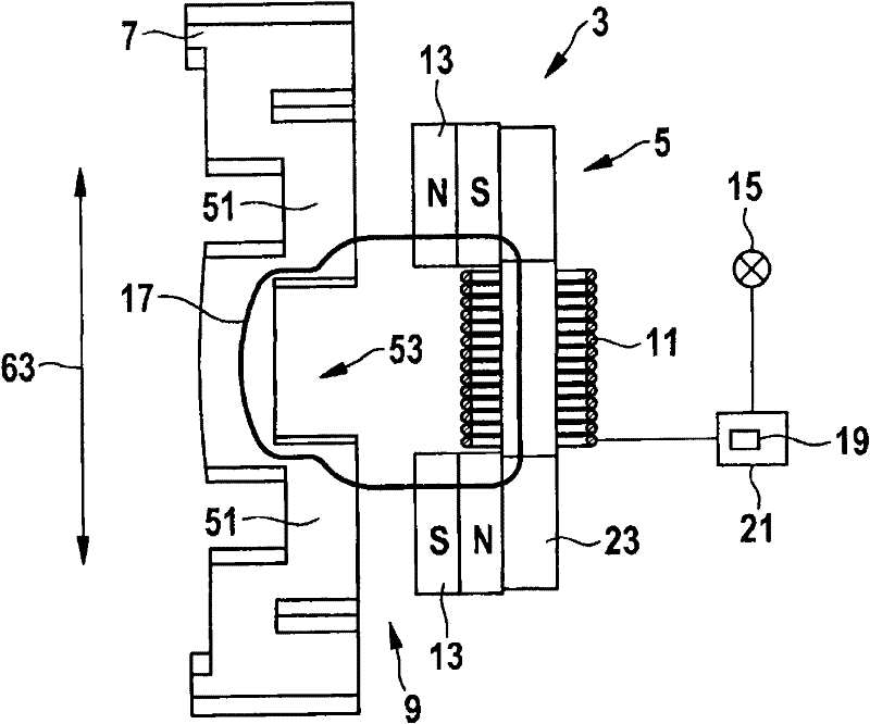
[0031] FIG. 2 shows a schematic diagram of the functional principle of the generator 3 of the machine tool 1 . Figure 2A and 2B Shown is a cross-sectional view of the generator 3 in different ...


PUM


Abstract

The invention relates to a machine tool with an electrical generator for passive power generation. The machine tool is provided with a generator (3) for generating electrical power is disclosed. The generator (3) has a rotor (7) and a stator (5). A coil (11) and a magnet (13) are arranged on the stator (5). The rotor (7) is capable of moving relative to the stator (5) and has a first region (51) and a second region (53). The rotor (7) is configured in such a way that, during a movement (63) of the rotor (7) relative to the stator (5), a magnetic flux in the coil (11) is changed due to differences between the first and second regions (51, 53) in terms of their magnetic permeability and / or in terms of their geometric configuration, and an electrical voltage is induced.

Description

technical field [0001] When working with machine tools, some auxiliary mechanisms are often required to optimize the working process, such as lighting the working surface with light-emitting devices. Background technique [0002] For example DE 10 2006 045157 A1 discloses a tool in which a light emitting device is integrated, but powering the light emitting device is a problem. Contents of the invention [0003] The object of the present invention is to provide an improved power tool that can be powered by auxiliary elements. [0004] This task is solved with the objects described in the independent claims of the present invention. Advantageous embodiments of the invention are described in the dependent claims. [0005] The features, details and advantages of the device of the present invention are discussed in detail below. [0006] According to a first aspect of the invention, a power tool, in particular a hand power tool, is specified, having a generator for generati...

Claims


Application Information

Patent Timeline
Patent Type & Authority Applications(China)
IPC IPC(8): H02K21/24B25F5/00
CPCH02K7/145H02K21/44H02K16/00B23Q17/2404H02K35/02H02K7/1166B25F5/00B25F5/021H02K7/1853H02K7/1876B23Q5/10
Inventor L·肖恩F·埃森魏因
Owner ROBERT BOSCH GMBH
Learn More