
Air-suspension air-supply-adjustable air blower directly driven by high-speed electric machine

A high-speed motor, air suspension technology, applied in the direction of machines/engines, mechanical equipment, liquid fuel engines, etc., can solve the problems of low power density, high gear transmission noise, high noise, improve the magnetic field strength and rotational speed, reduce noise and The effect of mechanical loss and improving the efficiency of the whole machine

Active Publication Date: 2011-09-28
宁波虎渡能源科技有限公司
View PDF8 Cites 13 Cited by
  • Summary
  • Abstract
  • Description
  • Claims
  • Application Information

AI Technical Summary

Problems solved by technology

However, the speed-up system is very complex, heavy, takes up a large area, and is expensive to manufacture. It needs a special matching lubricating oil system. The gear transmission noise is large and there is a certain mechanical loss; High; and both the speed-increasing system and the ordinary power-frequency motor need to use bearings. Due to the friction and life of the bearings, the rotation speed cannot be very high, resulting in low power density and huge volume of the system as a whole, and the power matching with the compressor impeller There are certain difficulties; and because the speed of the power frequency motor is constant, if you want to adjust the air supply volume of the blower, you must add a very complicated air intake control system, which increases the manufacturing cost and control difficulty

Method used


Image

  • Air-suspension air-supply-adjustable air blower directly driven by high-speed electric machine
  • Air-suspension air-supply-adjustable air blower directly driven by high-speed electric machine
  • Air-suspension air-supply-adjustable air blower directly driven by high-speed electric machine

Examples


Embodiment Construction

[0019] The present invention will be further described in detail with reference to the accompanying drawings and embodiments.

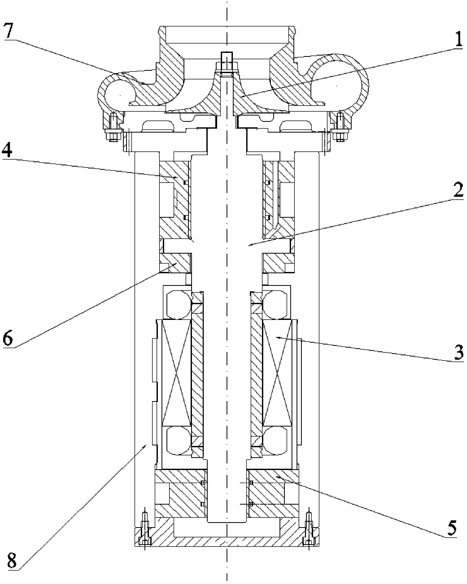
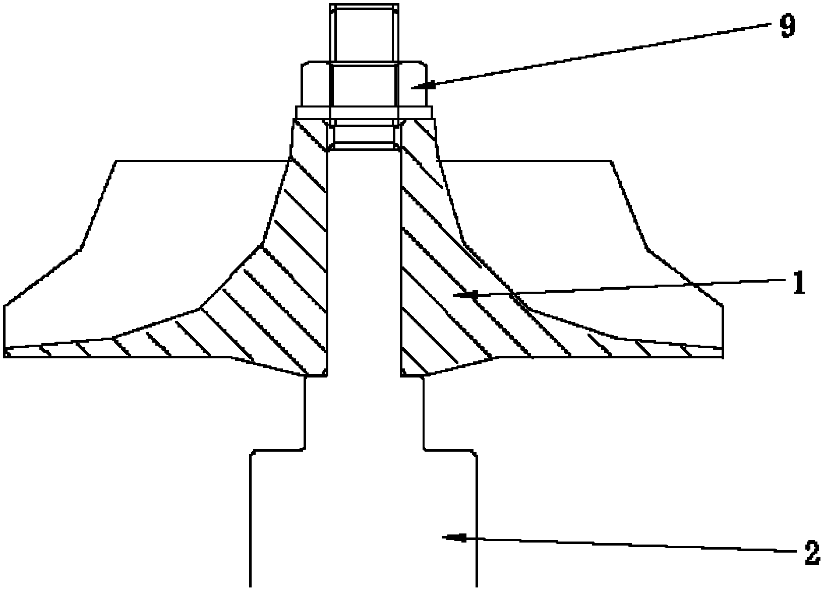
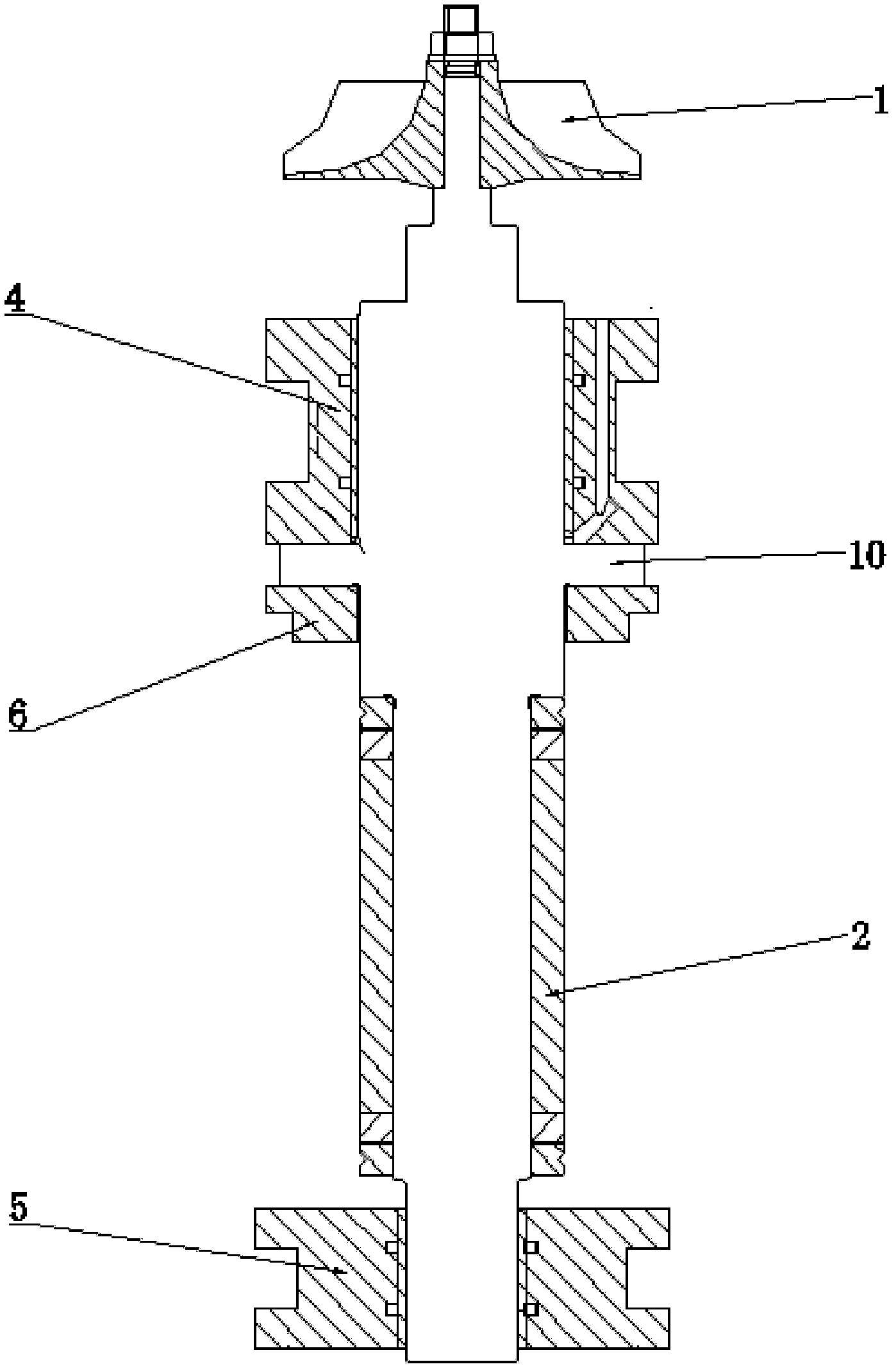
[0020] The invention is an air suspension air supply adjustable high-speed motor direct drive blower, such as figure 1 As shown, it includes compressor impeller 1, permanent magnet synchronous motor rotor 2, motor stator 3, front radial air bearing 4, rear radial air bearing 5, axial thrust air bearing 6, volute 7 and motor housing 8.

[0021] One end of the permanent magnet synchronous motor rotor 2 is connected to the compressor impeller 1, the motor stator 3 drives the permanent magnet synchronous motor rotor 2 to rotate, the front radial air bearing 4, the rear radial air bearing 5, and the axial thrust air bearing 6 are suspended and supported permanently Magnetic synchronous motor rotor 2, volute 7 surrounds compressor impeller 1, motor housing 8 surrounds motor stator 3, front radial air bearing 4, rear radial air bearing 5, axial thrust air b...


PUM


Abstract

The invention discloses an air-suspension air-supply-adjustable air blower directly driven by a high-speed electric machine. The air blower comprises a compressor impellor, a permanent magnetic synchronous motor rotor, a motor stator, a front radial air bearing, a rear radial air bearing, an axial thrust air bearing, a scroll and a motor shell; one end of the permanent magnetic synchronous motor rotor is connected with the compressor impellor; the rotor stator drives the permanent magnetic synchronous motor rotor to rotate; the front radial air bearing, the rear radial air bearing and the axial thrust air bearing support the permanent magnetic synchronous motor rotor in a suspension mode; the scroll is arranged at the periphery of the compressor impellor; and the motor shell is positioned at the peripheries of the motor stator, the front radial air bearing, the rear radial air bearing, the axial thrust air bearing and the permanent magnetic synchronous motor rotor. According to the invention, through driving the compressor impellor directly by the permanent magnetic synchronous motor rotor of the high-speed electric machine, a complex and expensive speeding system is omitted, noises and mechanical loss are reduced, the integral machine efficiency can be improved, the system is simple, and the air blower provided by the invention is convenient to install and transport.

Description

technical field [0001] The invention relates to an air suspension air supply adjustable high-speed motor direct-driven blower, which belongs to the technical field of blowers. Background technique [0002] The motor blower is a device that drives the impeller of the compressor to rotate under the action of electricity to do work on the air and increase the air pressure. Existing motor blowers usually use a speed-increasing system to drive the compressor impeller to rotate to do work after speeding up the common industrial frequency motor. However, the speed-up system is very complex, heavy, takes up a large area, and is expensive to manufacture. It needs a special matching lubricating oil system. The gear transmission noise is large and there is a certain mechanical loss; High; and both the speed-increasing system and the ordinary power-frequency motor need to use bearings. Due to the friction and life of the bearings, the rotation speed cannot be very high, resulting in lo...

Claims


Application Information

Patent Timeline
IPC IPC(8): F04D25/08F04D29/42F04D29/056
CPCF04D29/057
Inventor 侯安平
Owner 宁波虎渡能源科技有限公司
Learn More