
Electric connector for circuit substrate

A technology for circuit substrates and electrical connectors, which is applied to circuits, connections, and parts of connecting devices, etc., can solve the problems of reducing the amount of locking and falling off of flat conductors, and achieve the effect of preventing falling off and stable locking.

Active Publication Date: 2011-09-21
HIROSE ELECTRIC GROUP
View PDF8 Cites 8 Cited by
  • Summary
  • Abstract
  • Description
  • Claims
  • Application Information

AI Technical Summary

Problems solved by technology

That is to say, there may be a case where the flat conductor falls off unintentionally, such that the locking amount of the locking portion and the locked portion decreases or deviates.

Method used


Image

  • Electric connector for circuit substrate
  • Electric connector for circuit substrate
  • Electric connector for circuit substrate

Examples


Embodiment Construction

[0058] Embodiments of the present invention will be described below with reference to the drawings.

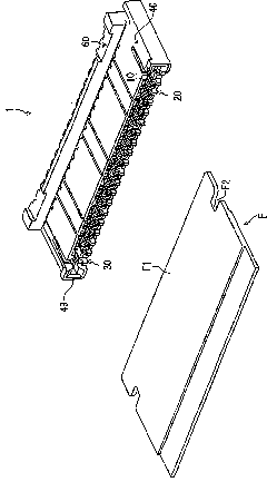
[0059] figure 1 It is a perspective view showing the whole of the electrical connector for a circuit board (hereinafter referred to as "connector") according to the present embodiment, and a connecting portion of the tip portion of a flat conductor connected to the connector.

[0060] In the flat conductor F, the covering part is removed on the lower surface of the front end to expose the conductor part (not shown), and the sheet-shaped reinforcing material F1 is attached to the upper surface so that it protrudes toward the connector 1 further forward than the conductor part. . In this reinforcing member F1 , notch-shaped locked portions F2 are formed on the left and right side edges further forward than the conductor portion.

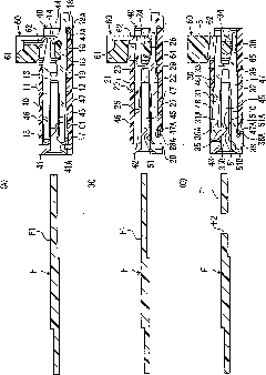
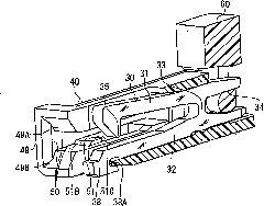
[0061] The connector 1 has terminals 10, 20 formed of metal plates, a lock fitting 30, a case 40 holding the terminals 10, 20, and the lock fitting ...


PUM


Abstract

The present invention provides an electric connector for a circuit substrate, which can prevent falling-off of a flat conductor. The electric connector of the invention is provided on the circuit substrate for electrically connecting the inserted flat conductor with the circuit substrate. A housing (40) or a component which is kept on the housing is provided with a higher projection (51) relatively to a carrying surface (52) for the insertion of the flat conductor (F), wherein a locking part (35) and the projection (51) vertically function vertically relatively to the flat conductor (F).

Description

technical field [0001] The invention relates to an electrical connector for a circuit substrate. Background technique [0002] This type of connector inserts and connects flat conductors such as FPCs in a state parallel to the surface of the circuit board. Generally speaking, the flat conductor is formed with an ear-shaped or hole-shaped locked part on its side edge, so that the locking part of the locking fitting of the connector is locked on the locked part, preventing the flat conductor from inadvertently fall off. [0003] In Patent Document 1, a locking fitting (locking member) having an upper arm and a lower arm connected by a connecting portion, substantially the same as a terminal (contact point), is provided in a horizontal H shape. The connecting portion extends horizontally toward the rear of the insertion side of the flat conductor, and a claw-shaped locking portion (engagement portion) is formed on the rear portion thereof. The locking portion is formed in a ...

Claims


Application Information

Patent Timeline
IPC IPC(8): H01R12/79H01R13/02H01R13/46H01R13/639H01R13/62
CPCH01R12/774H01R12/79H01R12/88H01R13/62994H01R13/639
Inventor 和田俊太郎玉木祥一郎
Owner HIROSE ELECTRIC GROUP
Learn More