Switching device

A switch device and closed position technology, which is applied in the direction of protection switch, circuit breaker contact, emergency protection device, etc., can solve the problem that the size design and configuration form of the contact pressure spring are not optimized.

Active Publication Date: 2014-12-31
SCHNEIDER ELECTRIC IND SAS
View PDF7 Cites 0 Cited by
  • Summary
  • Abstract
  • Description
  • Claims
  • Application Information

AI Technical Summary

Problems solved by technology

[0004] A disadvantage of this prior art circuit breaker is that the dimensioning and configuration of the contact biasing springs are not optimized

Method used


Image

  • Switching device
  • Switching device
  • Switching device

Examples


Embodiment Construction

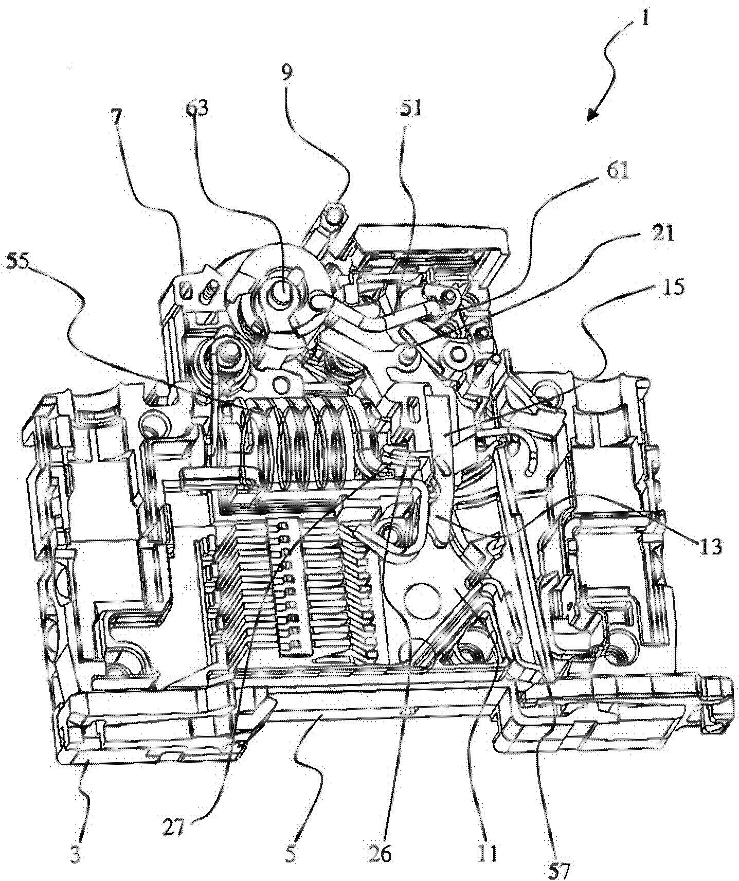
[0022] from figure 1 It can be seen that the circuit disconnector 1 comprises an insulating housing 3 mainly formed by two half-shells, the upper half-shell of which has been removed in order to be able to see the interior of said circuit disconnector. The housing 3 has a substantially parallelepiped shape corresponding to the modular system. The housing 3 has a rear side panel 5 and a front side panel 7 , the rear side panel 5 is used to be fixed on the guide rail, and the front side panel 7 has a hole through which the operating handle 9 passes. The circuit breaker 1 comprises a neutral breaking circuit and a phase breaking circuit respectively arranged on each side of an insulating separator 11 interposed between the two half-shells and extending parallel to the main panel of the housing 3 . exist figure 1 In , only the phase breaking circuit can be seen, while the neutral breaking circuit is located behind the insulating divider 11 .

[0023] The phase breaking circuit ...


PUM


Abstract

#CMT# # / CMT# The device has a phase mobile contact and a neutral mobile contact that are carried by a first end of contact arms. Each arm is mounted around a pivot (21) for allowing pivoting of the arm toward a closing position of the contacts. Contact pressure units comprise two torsion springs acting independently and respectively on the contact arms. Each spring is arranged with respect to the arms on which the springs act such that a rotation axis of the springs is shifted toward a second end of the arms with respect to a pivot axis. #CMT#USE : # / CMT# Cut-off device for use in a circuit breaker e.g. single-pole circuit breaker and neutral circuit breaker, utilized in distribution installations i.e. buildings, to protect an electrical circuit. #CMT#ADVANTAGE : # / CMT# The contact pressure units comprise the torsion springs that are arranged with respect to the contact arms on which the springs act such that the rotation axis of the springs is shifted toward the second end of the arms with respect to the pivot axis so as to allow the springs to be positioned with respect to a shaft in simple and easy manner, thus reducing force exerted by the springs on the contact arms and reducing dimensions of the pressure units, and hence reducing complexity of a control mechanism of the device. #CMT#DESCRIPTION OF DRAWINGS : # / CMT# The drawing shows a partial view of a cut-off device with a control mechanism in which one of contact arms permits visualization of a support lever and contact pressure units. 21 : Pivot 41 : Support lever 51 : Tie rod 61 : Mechanical connection 63 : Pivot pin.

Description

technical field [0001] The invention relates to the field of switching devices of the circuit breaker or differential circuit breaker type, in particular single-pole plus neutral circuit breakers. Such circuit breakers are commonly used in terminal distribution facilities, especially buildings, to protect the circuit by interrupting both the phase and neutral conductors. [0002] In particular, the invention relates to a switchgear having an insulating housing accommodating a movable contact comprising at least one phase movable contact and a neutral one respectively supported by first ends of at least two contact arms Movable contacts, each contact arm mounted about a pivot pin to allow rotation of said contact arm to a closed position of said contact, said means comprising a contact pressure applied to said contact arm contact pressure tool. Background technique [0003] Patent application EP0042778 describes a single pole plus neutral circuit breaker comprising two mova...

Claims


Application Information

Patent Timeline
Patent Type & Authority Patents(China)
IPC IPC(8): H01H71/10H01H73/04
CPCH01H71/002H01H71/522H01H71/526
Inventor 伊维斯.贝林克里斯托弗.米切洛特
Owner SCHNEIDER ELECTRIC IND SAS
Why Eureka
Try Eureka