Knitted fabric and knitting method thereof, and designing apparatus
A technology of knitted fabrics and knitted yarns, which is applied in the field of knitted fabrics, can solve problems such as stays, and achieve the effect of shortening the knitting process
- Summary
- Abstract
- Description
- Claims
- Application Information
AI Technical Summary
Problems solved by technology
Method used
Image

Examples
Embodiment 1
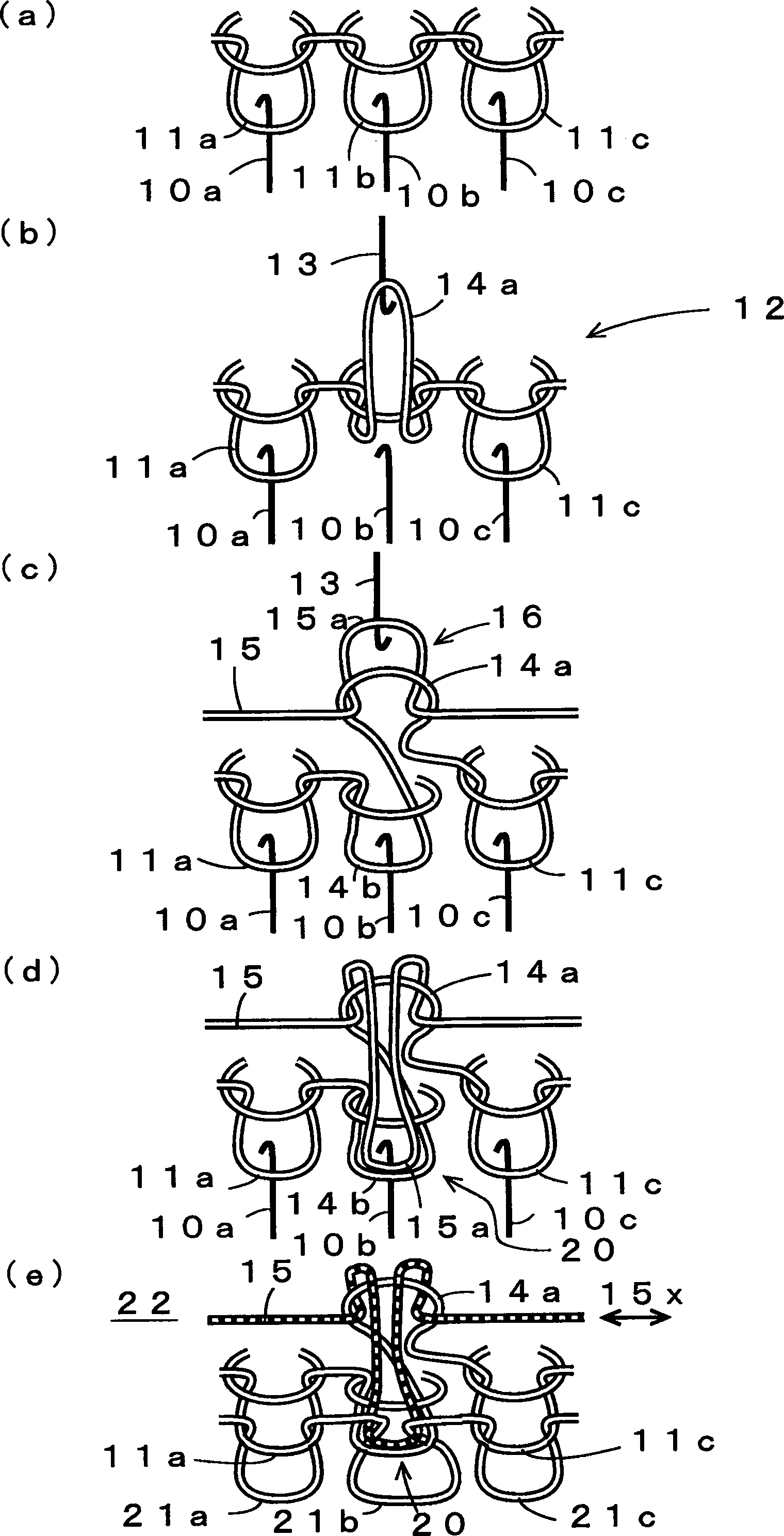
[0045] figure 1 The structure of the stitch which is the main part of the knitting method of one embodiment of this invention is shown schematically. (a) shows for example in Figure 5 The stitches 11a, 11b, and 11c are formed by one course on the latch needles 10a, 10b, and 10c of the front needle bed. (b) shows the following state: one stitch 11b held by the latch needle 10b as the holding knitting needle among the latch needles 10a, 10b, 10c in (a) is transferred to the rear needle bed opposite to the latch needle 10b at the tooth gap 12 The latch needle 13 hooks the coil 14a. (c) shows the state where the minute transfer 16 is performed between the latch needles 10b and 13 of the front and rear needle beds when the knitting yarn as the transition yarn 15 is knitted. The minute hand stitch transfer 16 is carried out for the stitch 14a after the stitch transfer in (b), and the transition yarn 15 is caught on the hook of the latch needle 13 as the rear needle bed of the op...
Embodiment 2
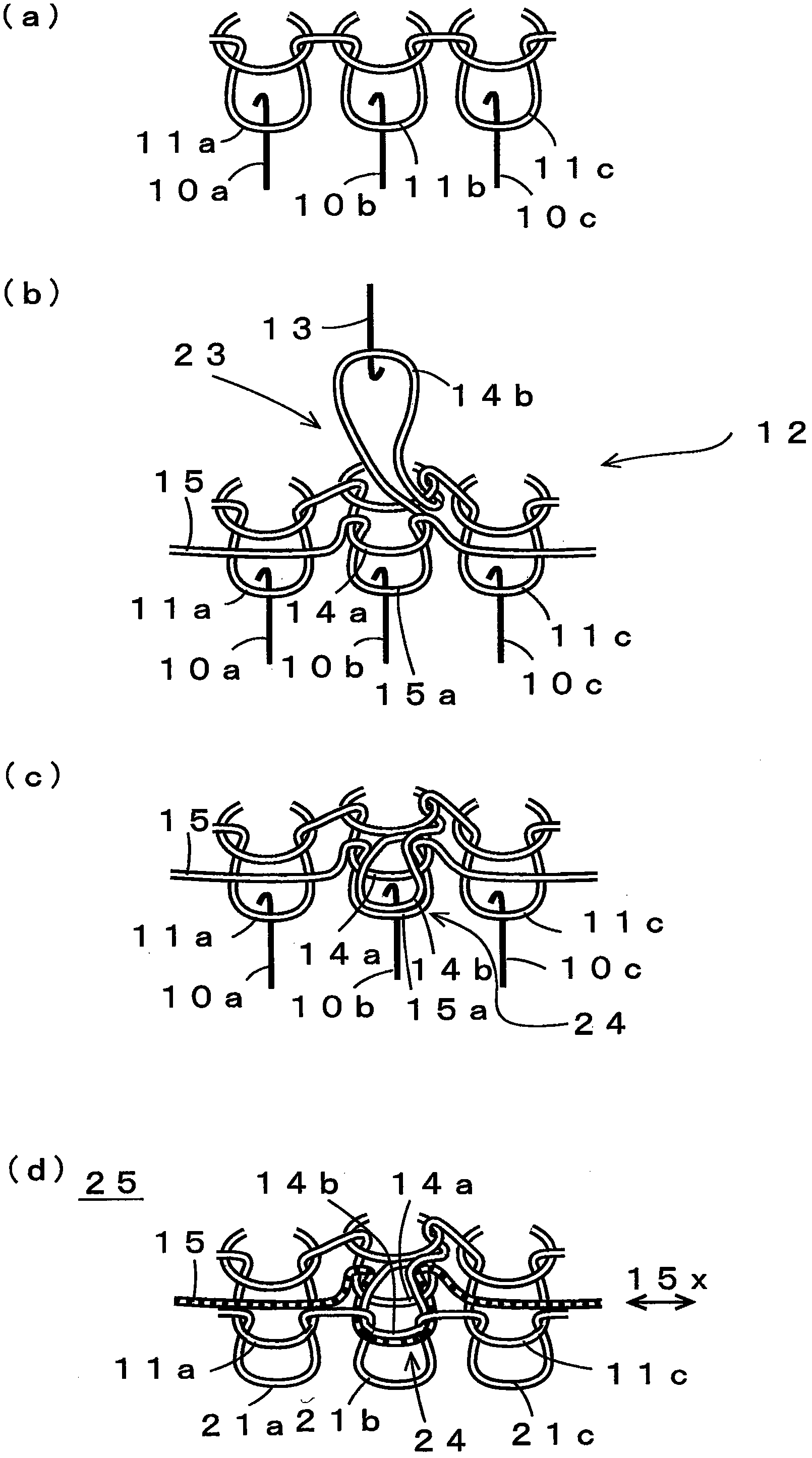
[0053] image 3 , schematically shows the configuration of the stitches that are the main part of the knitting method in another embodiment of the present invention. (a) with figure 1 (a) similarly shows a state in which the stitches 11a, 11b, and 11c are formed on the latch needles 10a, 10b, and 10c of the front needle bed by one course. (b) shows a state in which the transition yarn 15 is caught on the hook of the latch needle 10b as the holding knitting needle by the transfer 23 of the minute hand when knitting the knitting yarn as the transition yarn 15 to form a stitch 15a as a new stitch , and a part of the retained stitch 11b is taken off as the stitch 14a of the old stitch, and the stitch 14b is formed by transfer on the latch needle 13 as the facing knitting needle. (c) shows the following state: the stitch 14b transferred to the latch needle 13 by the minute hand transfer 23 of (b) is transferred to the original latch needle 10b and then returned to overlap with t...
Embodiment 3
[0055] Figure 4 A schematic configuration of a design device 30 as yet another embodiment of the present invention is shown. The design device 30 generates knitting data necessary for knitting knitted fabrics using a flat knitting machine in which at least a pair of front and rear needle beds are arranged so as to face each other at the needle bed 12, such as the front needle bed and the rear needle bed. On the needle bed, a plurality of latch needles 10a, 10b, 10c, and 13 are respectively arranged as knitting needles. The design device 30 is realized by installing software for designing knitted fabrics in a general-purpose computer 31 . In the computer 31 , various input operations can be performed using the input device 32 , and display of operation results, processing results, and the like can be performed via the display device 33 . The communication device 34 can be used for downloading of software and communication of data. The storage device 35 can be used for stora...
PUM
 Abstract
Description
Claims
Application Information
 - R&D
- Intellectual Property
- Life Sciences
- Materials
- Tech Scout
- Unparalleled Data Quality
- Higher Quality Content
- 60% Fewer Hallucinations
Browse by: Latest US Patents, China's latest patents, Technical Efficacy Thesaurus, Application Domain, Technology Topic, Popular Technical Reports.
© 2025 PatSnap. All rights reserved.Legal|Privacy policy|Modern Slavery Act Transparency Statement|Sitemap|About US| Contact US: help@patsnap.com