Microwave power confocal synthesis device
A microwave power and synthesis device technology, which is applied in the cross-field of ion technology, can solve the problems of complex system structure, high cost, and high microwave source requirements, and achieve the effect of increasing microwave power, cheap price, and reducing cost
- Summary
- Abstract
- Description
- Claims
- Application Information
AI Technical Summary
Problems solved by technology
Method used
Image


Examples
Embodiment 1
[0021] see figure 1 , where a is the main view, b is the left view, and c is the top view. The microwave power confocal synthesis device in this example includes a microwave input terminal A and a microwave input terminal B, and their corresponding waveguide cavities are waveguide cavity 1 and waveguide cavity 2 respectively, and waveguide cavity 1 and waveguide cavity 2 are connected to form a confocal cavity. The side walls 10 and 20 of the waveguide cavity 1 and the waveguide cavity 2 are perpendicular to the bottom surface 11 and the top surface 12, and the orthographic projections of the side walls 10 and 20 on the bottom surface 11 and the top surface 12 are elliptical arcs, see figure 1 a. The two focal points of the waveguide cavity 1 are A and O respectively, and the two focal points of the waveguide cavity 2 are B and O respectively. The focal point O is the common focal point of the waveguide cavity 1 and the waveguide cavity 2, that is, the microwave converging e...
Embodiment 2
[0023] Such as figure 2 As shown in the figure, a is the main view, b is the left view, and c is the top view. The microwave power confocal combining device in this example is a 3-input microwave power combiner, which is composed of 3 waveguide cavities with the same structure. These 3 waveguide cavities are evenly distributed in space, and their microwave input ends are image 3 In a, marked as A, B and C, they are respectively located at a focal point of waveguide cavity 1, waveguide cavity 2 and waveguide cavity 3, and these three microwave input ports are located at the vertices of the regular triangle surrounded by ABC. The other focal points of these three waveguide cavities coincide together and are located at the center of the equilateral triangle ABC, becoming the converging end of this example, that is image 3The public focus O in a. In the confocal cavity formed by the waveguide cavity 1, the waveguide cavity 2 and the waveguide cavity 3, the three input ends ar...
Embodiment 3
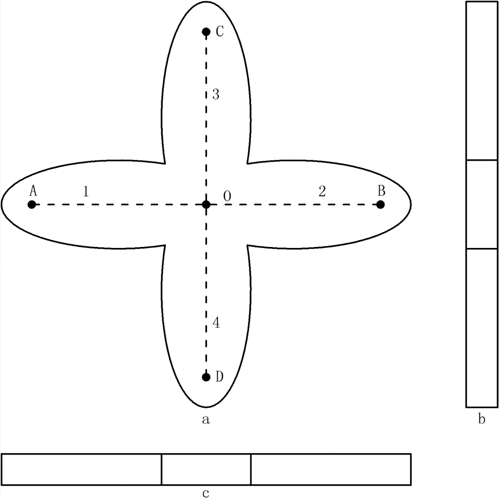
[0025] Such as image 3 As shown in the figure, a is the main view, b is the left view, and c is the top view. The microwave power confocal combining device in this example is composed of four waveguide cavities with the same structure, see image 3 Waveguide cavity 1, waveguide cavity 2, waveguide cavity 3 and waveguide cavity 4 in a. The side walls of the four waveguide cavities are perpendicular to the bottom surface and the bottom surface of the waveguide cavity, and the orthographic projections on the bottom surface and the bottom surface of the waveguide cavity are uniform elliptical arcs. One focus of the four waveguide cavities coincides, which is the common focus O in this example, and the other focuses of the four waveguide cavities are respectively A, B, C, and D, which are located at the endpoints of two vertical straight lines (straight line AB and straight line CD), In this example, the four microwave input ends are respectively placed on the four focal points,...
PUM
 Abstract
Description
Claims
Application Information
 - Generate Ideas
- Intellectual Property
- Life Sciences
- Materials
- Tech Scout
- Unparalleled Data Quality
- Higher Quality Content
- 60% Fewer Hallucinations
Browse by: Latest US Patents, China's latest patents, Technical Efficacy Thesaurus, Application Domain, Technology Topic, Popular Technical Reports.
© 2025 PatSnap. All rights reserved.Legal|Privacy policy|Modern Slavery Act Transparency Statement|Sitemap|About US| Contact US: help@patsnap.com