
Drawing and model integrated visual integration design method

An integrated design and graphics-model integration technology, applied in calculation, special data processing applications, instruments, etc., can solve the problem that the relevant information is not intuitive and clear, it is not conducive to the coordination of installation and adjustment work, and it is not conducive to the standardization and standardization of the secondary system integration work of substations. and other issues to achieve the effect of reducing repeated information exchange, improving design efficiency, and shortening design time

Inactive Publication Date: 2011-09-14
GUANGXI ELECTRIC POWER IND INVESTIGATION DESIGN & RES INST
View PDF0 Cites 26 Cited by
  • Summary
  • Abstract
  • Description
  • Claims
  • Application Information

AI Technical Summary

Problems solved by technology

The design of digital substation relies too much on the system manufacturer, and the leading position of the design unit is relatively weakened during the implementation of the project, which is not conducive to the standardization and standardization of the secondary system integration work of the substation, and is not conducive to the coordination of installation and adjustment work, and is not conducive to the future Expansion, transformation and equipment update of substation projects; (2) Increased visibility of operation and maintenance
Although the SCD file provided by the system manufacturer contains the integration information of the entire system, the relevant information is not intuitive and clear, and cannot directly reflect the connection relationship and data flow direction between various IED devices. For equipment installation and operation and maintenance personnel, the network The transmitted information is opaque, which brings great inconvenience to the installation, commissioning, operation and maintenance of the equipment

Method used


Image

  • Drawing and model integrated visual integration design method
  • Drawing and model integrated visual integration design method
  • Drawing and model integrated visual integration design method

Examples


Embodiment 1

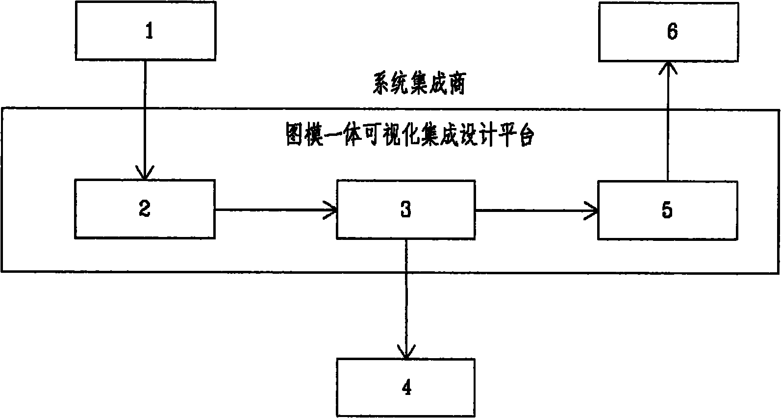
[0050] This method is applied to the design of the as-built drawing of the "Establishment of 500kV Complete Digital Substation Pilot Project". Further elaborate below in conjunction with specific embodiment, design step is as follows, as image 3 Shown:

[0051] 1. IED equipment manufacturers provide ICD model files of PSL603UW line protection, PSL602U line protection, PCS931 line protection, SGB750 busbar protection, PSL632U circuit breaker protection and PSR662U measurement and control device required for the project to the system manufacturer.

[0052] 2. The system manufacturer uses the graphic-model integrated visual integrated design software to verify whether the syntax of all models is standardized. According to the scale of this project, assign IP addresses to the equipment used in this project, assign multicast addresses and AppIDs according to the number of configuration control blocks in each device model file, and divide VLANs according to the requirements of net...


PUM


Abstract

The invention discloses a drawing and model integrated visual integration design method. A design institute and a system manufacturer take the responsibility of a system integrator together to finish the work of a designing a drawing for a transform substation and modeling all-station information. In the method, secondary development is performed on an Auto computer-aided design (CAD) by adopting an ActiveX Automation technology by taking the AutoCAD as an information interaction platform so as to establish a native XML database (NXD)-based model text storage database. By adopting the drawing and model integrated integration design, both a design drawing and a model file provided by the design institute can be identified; the bonding of information is finished by the design method so that a CAD file which is finally provided for a user can not only display connection information in the model in a visual mode, but also export the model file for a required unit, a manufacturer or a system to use, and realize the bidirectional switching of the drawing and the model.

Description

technical field [0001] The invention belongs to the field of power system design. Specifically, it is the realization method of visual integrated design of graph-model integration. Background technique [0002] Digital and intelligent substations generally adopt the IEC 61850 standard. According to the definition of IEC 61850, the information exchange files in the substation are various model files in XML format. At present, the commonly used method for digital station design is: IED equipment manufacturers provide device schematic diagrams and screen diagrams, and the design unit draws primary and secondary equipment and network wiring diagrams according to project conditions. Tools, system configuration tools, engineering configuration work, etc. are mostly in the charge of equipment manufacturers, while system integration is completed by system manufacturers and provides SCD files. It can be seen that the system manufacturer plays a key role in the model configuration p...

Claims


Application Information

Patent Timeline
Patent Type & Authority Applications(China)
IPC IPC(8): G06F17/50
Inventor 曹珍祟黄伟陈娟陆以夫陆忻秦征周哲吴皓李磊任怀兵陈明华常红梅潘济猛
Owner GUANGXI ELECTRIC POWER IND INVESTIGATION DESIGN & RES INST
Learn More