ERG (exhaust gas recirculation) mixer

A mixer and cavity technology, which is used in machines/engines, adding non-fuel substances to fuel, internal combustion piston engines, etc., can solve the problem that the mixing uniformity of recirculated exhaust gas can no longer meet the requirements of stable operation of the engine, and the intake pipeline is short. and other problems, to achieve the effect of improving mixing uniformity and mixing efficiency, compact structure and cost saving

Inactive Publication Date: 2011-09-14
CHERY AUTOMOBILE CO LTD
View PDF4 Cites 18 Cited by
  • Summary
  • Abstract
  • Description
  • Claims
  • Application Information

AI Technical Summary

Problems solved by technology

Now with the improvement and maturity of EGR technology, the amount of circulating exhaust gas (EGR rate) is increasing, and the requirement of engine compactness makes the intake pipeline shorter, so the recirculating exhaust gas (EGR) obtained by using the traditional method The mixing uniformity of fresh air can no longer meet the requirements of stable engine operation

Method used


Image

  • ERG (exhaust gas recirculation) mixer
  • ERG (exhaust gas recirculation) mixer
  • ERG (exhaust gas recirculation) mixer

Examples


Embodiment 1

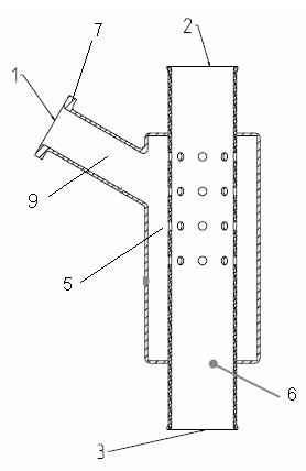
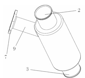
[0019] Such as figure 1 , 3 As shown, the EGR mixer of this embodiment includes a second cavity 5 and a straight cylindrical first cavity 6, the first cavity 6 includes a first air inlet 2 and an air outlet 3, and the second cavity 5 includes a first Two air inlets 1, the second cavity 5 communicate with the inside of the first cavity 6 through a plurality of ventilation holes 4 on the wall of the first cavity 6, and the ventilation holes 4 are distributed in the first cavity 6 in a ring shape Around the wall of the cavity to improve the mixing uniformity of fresh air and EGR exhaust gas; the second cavity 5 is provided with an intake pipe 9 facing the wall of the first cavity 6, and the second air inlet 1 is arranged at the end of the intake pipe 9 part, and is provided with a connecting flange 7.

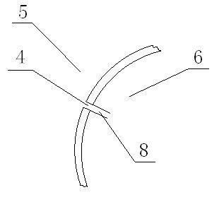
[0020] Such as figure 2 As shown, the vent hole 4 is provided with a guide tube 8 towards the inside of the first cavity 6, so that the gas entering the first cavity 6 through...


PUM


Abstract

The invention provides an EGR (exhaust gas recirculation) mixer with small occupied space and high mixing efficiency. The EGR mixer comprises a first chamber and a second chamber, wherein the first chamber includes a first air inlet and an air outlet, the second chamber includes a second air inlet, and the second chamber is communicated with the interior of the first chamber through a plurality of air vents arranged on the walls of the first chamber. Fresh air and EGR exhaust gas can respectively enter the chamber through the first air inlet and the second air inlet and can be uniformly mix in the first chamber due to the mutually vertical flow directions. The EGR mixer provided by the invention has a small and exquisite structure; as two chambers are arranged, the flow directions of the exhaust gas and the fresh air can be vertical, thus improving the mixing uniformity and the mixing efficiency without increasing the length of air inlet pipelines; and the exhaust gas and the fresh air can be completely and uniformly mixed before entering the engine cylinder, thus satisfying the steady operation of the engine. Besides, a pressure-regulating valve is not needed to be additionally installed in the use of the EGR mixer; therefore, the costs can be saved.

Description

technical field [0001] The invention belongs to the technical field of automobile engine manufacture, and in particular relates to an EGR mixer used in an internal combustion engine with an exhaust gas recirculation device (EGR). Background technique [0002] Exhaust Gas Recirculation (Exhaust Gas Recirculation) refers to the technology of introducing part of the exhaust gas into the intake air for re-combustion after the internal combustion engine of an automobile is burned, which can reduce nitrogen oxides (NOx) in the exhaust gas and improve fuel economy. With the increasingly stringent emission regulations and rising fuel prices, EGR technology is more and more widely used in engines. In the past, recirculated exhaust gas had a long pipeline to mix with fresh air before entering the cylinder, and the amount of recirculated exhaust gas (EGR rate) introduced was low, so there was no specially designed EGR mixer. Now with the improvement and maturity of EGR technology, the...

Claims


Application Information

Patent Timeline
Patent Type & Authority Applications(China)
IPC IPC(8): F02M25/07F02M26/19
CPCY02T10/121Y02T10/12
Inventor 熬艳平刘和义刘国庆
Owner CHERY AUTOMOBILE CO LTD
Why Eureka
Try Eureka