Eureka AIR delivers breakthrough ideas for toughest innovation challenges, trusted by R&D personnel around the world.

Large swirl injection flotation column

A flotation column and swirl technology, applied in flotation, solid separation and other directions, can solve problems such as inability to break through, dead ends of tailings and slag deposition, and bottlenecks encountered in large-scale flotation columns, so as to improve concentrate grade and recovery rate. Improved, prolonged flotation time effect

Inactive Publication Date: 2011-09-14
李宾
View PDF5 Cites 11 Cited by
  • Summary
  • Abstract
  • Description
  • Claims
  • Application Information

AI Technical Summary

Problems solved by technology

[0004] However, the maximum diameter of the flotation column in the prior art of this swirl jet flotation machine can only be 5 meters, and the single tank is 50m 3 The processing capacity is 2000 tons per 24 hours
If the flotation column is larger, there will be a problem of tailings and slag deposition at the bottom of the flotation column, which makes the large-scale flotation column using swirl jet instead of conventional stirring device encounter a bottleneck and cannot break through. This kind of flotation effect is good and the structure The swirling jet flotation machine, which is simple and convenient to use and maintain, cannot meet the needs of large-scale development of mining enterprises
[0005] Therefore, the large-scale flotation columns in the prior art still all adopt the structure of the built-in stirring device, and cannot use the swirl jet aerator

Method used


Image

  • Large swirl injection flotation column
  • Large swirl injection flotation column
  • Large swirl injection flotation column

Examples


Embodiment Construction

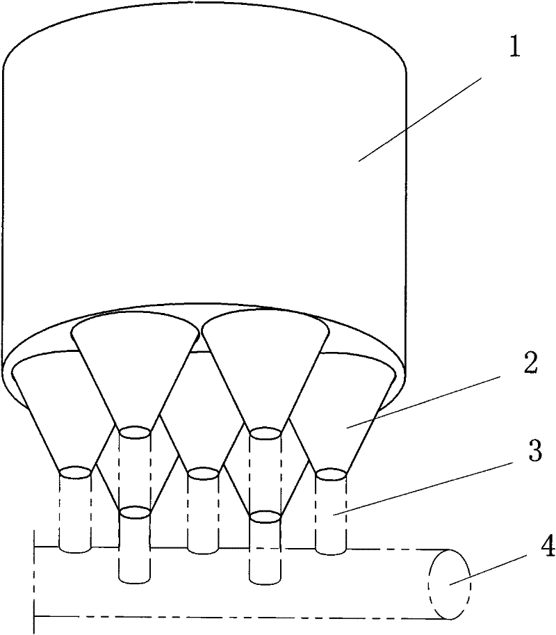
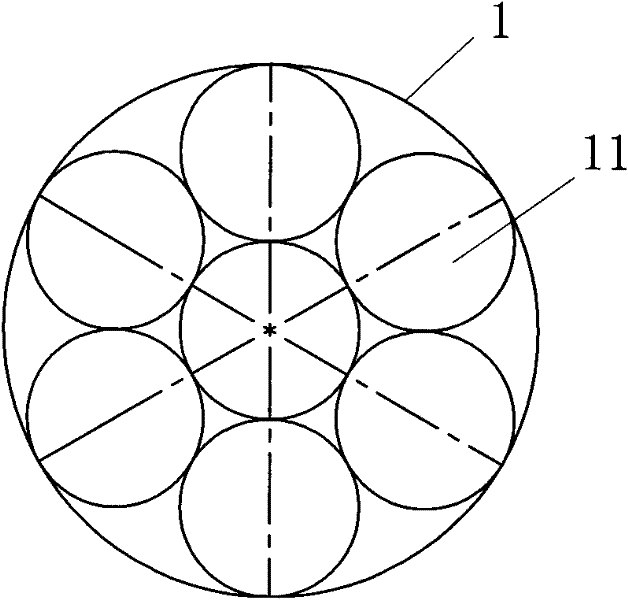
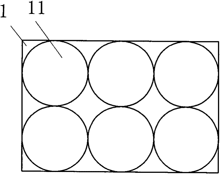
[0035] Such as figure 1 and Figure 4 Shown, a kind of large swirl jet flotation column provided by the present invention, its diameter is greater than 5 meters. The flotation column includes a flotation column cavity 1, an opening on the outer wall of the flotation column cavity 1, connected to a pulp inlet pipe 11, a swirl jet aerator 12 is installed on the pulp inlet pipe, and the flotation column The bottom of cavity 1 is provided with more than one opening. In this embodiment, seven openings 13 are provided. Below each opening 13, a tapered outlet pipe 2 is connected for tailings discharge. The area of ​​the outlet end of the outlet pipe is less than The area of ​​the opening at the bottom of the cavity is a tapered tube 2 with a large top and a small bottom.

[0036] This tapered pipe 2 is preferably swirl tapered pipe 21, namely as Figure 5 , 6 As shown, a spiral rib 21a is provided on the inner wall of the tapered pipe, so that the tailings slurry flowing through ...


PUM

PropertyMeasurementUnit
Cone angleaaaaaaaaaa

Abstract

The invention provides a large swirl injection floatation column, which comprises a floatation column cavity. The outer wall of the floatation column cavity is provided with an opening connected with an ore pulp inlet pipe; a swirl injection aerator is arranged on the ore pulp inlet pipe; and the bottom of the floatation column cavity is provided with more than one opening below which a tailing discharge pipe; and the tailing discharge pipe has a large upper part and a small lower part. In the floatation column, the lower bottom surface is provided with openings connected with conical pipes, namely conical tailing discharge holes are equally divided, a tailing slag sedimentation dead angle does not occur at the bottom of the floatation column without a stirring device, a problem that large tailing discharge holes of the floatation column are blocked is solved, the swirl injection aerator is used for conveying ore pulp in the large floatation column, the diameter of the swirl injectionfloatation column is increased to 5-15 meters, and the single-trough treatment capacity is improved to 2,000-20,000 tons of dry ore per 24 hours, so that the floatation time of the large floatation column is prolonged, the recovery rate can be improved by 1-3 percent, the grade of concentration can be improved, the treatment capacity is improved and energy is greatly saved.

Description

technical field [0001] The invention belongs to the technical field of mineral flotation, and relates to a mineral flotation device, in particular to a large swirling jet flotation column. Background technique [0002] In the prior art, the flotation equipment used in mineral flotation includes flotation columns. The slurry containing the flotation agent entrains a large amount of air into the flotation column, where it is fully mixed, and then stratified, and the flotation concentrate is carried in the foam, which is discharged from the upper outlet of the flotation column, and the tailings solid deposits At the bottom of the flotation column, the flotation column is discharged through the U-shaped tailings discharge pipeline. In the flotation column commonly used in the prior art, in order to fully mix and contact the air, chemicals and minerals in the pulp, a stirring device should be installed in the flotation column. This device can also prevent tailings solids from de...

Claims


Application Information

Patent Timeline
IPC IPC(8): B03D1/14
CPCB03D1/1418B03D1/1468
Inventor 李宾
Owner 李宾
Why Eureka
Eureka Blog
Learn More