


Quick Research
Generate reliable direction feasibility study reports for your R&D in just a few steps.

Technical Q&A
Discover and master advanced knowledge NOW. Basics, ideas, possibilities, all at once.

Find Solutions
As an expert in R&D theories, this can generate solutions to your technical problems instantly.

Evaluate Feasibility
Analyze your overall solution with one click, know your potential R&D risks in advance.

Monitor Landscape
Get weekly tech updates, stay abreast of the latest tech innovations and key insights.
Medium-pressure gas collection technique based on cluster well
A process method, cluster well technology, applied in the direction of earthwork drilling, wellbore/well components, production fluid, etc., can solve the problems of increasing engineering investment and operating costs, unfavorable utilization of formation pressure, high design pressure of alcohol injection pipelines, etc. , to achieve the effect of improving liquid carrying capacity, convenient management, and small maintenance workload
- Summary
- Abstract
- Description
- Claims
- Application Information
AI Technical Summary
Problems solved by technology
Method used
Image


Examples
Embodiment 1
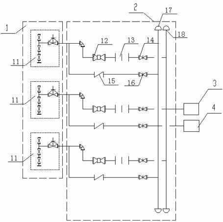
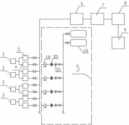
[0019] Such as figure 1 , figure 2 As shown in the structural diagram of the medium pressure gas gathering process, it includes cluster well group 1, wellhead device 2, gas production branch line 3, alcohol injection pipeline 4, alcohol injection device 5, gas production main pipe 6, gas gathering station 7. Gas gathering branch line 8. Central processing plant 9.
[0020] The cluster well group 1 is composed of 3 to 9 natural gas wells 11. There are downhole chokes in the gas wells 11. The distance between the downhole chokes and the wellhead device is 1500 meters to 3000 meters. Each gas well 11 passes through the downhole chokes. Reduce the wellhead pressure to medium pressure, and then through the wellhead device 2 and the gas production branch line 3, the natural gas generated by each gas well 11 of the cluster well group 1 is metered and transported to the next collected well group, and the surrounding cluster well group 1 gathers Afterwards, it is transported to the ...
Embodiment 2
[0024] The wellhead device 2 in the foregoing embodiment comprises a wellhead shut-off valve 12, a flow meter 13, a natural gas shut-off valve 14, a check valve 15, a methanol shut-off valve 16, a methanol manifold 17, and a natural gas manifold 18. The wellhead of the gas well 11 is divided into two One of them connects the wellhead shut-off valve 12, the flow meter 13, and the natural gas shut-off valve 14 in series to form a natural gas pipeline, and the natural gas manifold 18 gathers the natural gas pipelines of other gas wells 11 in the cluster well group 1 Afterwards, it is connected with the gas production branch line 3; the other one connects the check valve 15 and the methanol shut-off valve 16 in series and connects them with the methanol manifold 17 to form an alcohol injection pipeline. After the alcohol pipelines are collected, they are connected with the alcohol injection pipeline 4, and the check valve 15 ensures that natural gas will not enter the alcohol injec...
Embodiment 3
[0026] The alcohol injection device 5 in embodiment 1 is made up of methanol storage tank 10, alcohol injection pump 19, methanol flowmeter 20, filter 21, and the alcohol injection pipeline 4 connected to each gas well 11 all passes through alcohol injection pump 19, methanol flow rate respectively. A meter 20 and a filter 21 are connected to the outlet end of the methanol storage tank 10 in sequence.
[0027] The methanol in the methanol storage tank 10 is filtered and measured by the filter 21 and the methanol flowmeter 20, and after being pressurized by the alcohol injection pump 19, the methanol in the methanol storage tank 10 is injected into the gas well 11 through the alcohol injection pipeline 4, and the methanol and natural gas pass through the wellhead together. The natural gas pipeline of device 2 enters the gas extraction branch line 3 .
PUM
 Abstract
Description
Claims
Application Information
 - R&D Engineer
- R&D Manager
- IP Professional
- Industry Leading Data Capabilities
- Powerful AI technology
- Patent DNA Extraction
Browse by: Latest US Patents, China's latest patents, Technical Efficacy Thesaurus, Application Domain, Technology Topic, Popular Technical Reports.
© 2024 PatSnap. All rights reserved.Legal|Privacy policy|Modern Slavery Act Transparency Statement|Sitemap|About US| Contact US: help@patsnap.com