End face tooth engaged and separated structure for speed reducer of mowing machine

A technology of end-face gear meshing and separation structure, which is applied in the direction of harvesters, agricultural machinery and implements, etc. It can solve the problems of slipping, unable to go uphill, unable to work effectively, and affect the service life, so as to improve the strength and speed of engagement or separation , climbing speed and mowing efficiency are improved, and the service life is extended

Inactive Publication Date: 2011-09-07
YUYAO SOBO GARDEN MACHINERY
View PDF8 Cites 4 Cited by
  • Summary
  • Abstract
  • Description
  • Claims
  • Application Information

AI Technical Summary

Problems solved by technology

[0002] Lawn mowers used in places such as urban green belts generally use worm gear reducers to achieve the purpose of small size, light weight, and durability, especially the use of worm gear reducers to output drive travel mechanisms has been widely used. The drive reduction box for grass machine, because the linkage device of the worm gear reducer is fixed on the power output shaft of the running mechanism in the circumferential direction by the friction cone, the engagement and separation are realized by the axial friction force, and the friction force depends on the curved dial. The rod exerts pressure on the friction cone to achieve it, so it usually needs to maintain enough maintaining force to work effectively. The operator is very laborious and difficult to master. The operating force is too light to work, and the operating force is too heavy. Too heavy will cause the cone surface to wear, and the cone surface will slide and fail. The friction loss caused by the large enough friction will also seriously affect the service life. Tighten the friction force to the maximum and it will not work effectively, resulting in slippage and unable to go uphill, or even fall back and cause an accident

Method used


Image

  • End face tooth engaged and separated structure for speed reducer of mowing machine
  • End face tooth engaged and separated structure for speed reducer of mowing machine
  • End face tooth engaged and separated structure for speed reducer of mowing machine

Examples


Embodiment Construction

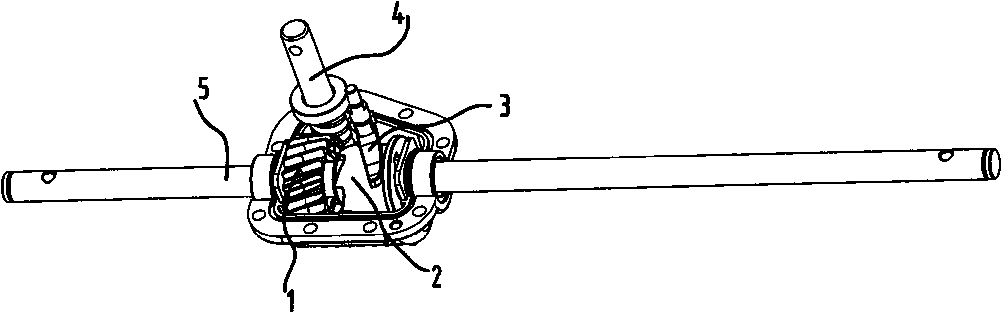
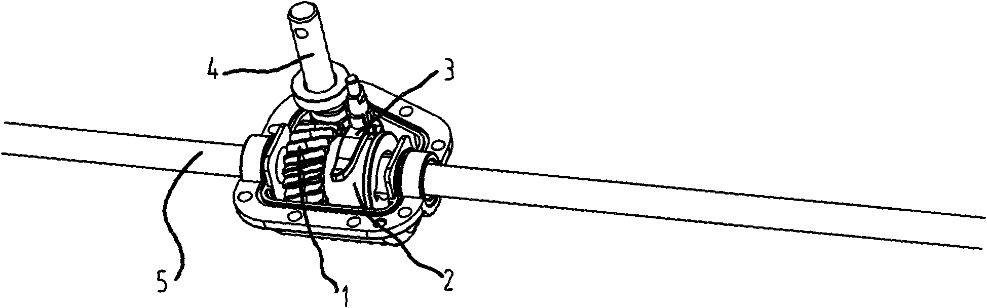
[0012] Figure 1a with Figure 2a Shown is the three-dimensional structure diagram of the present invention after the reduction box cover is removed, the lower end of the power input shaft is a worm 4 with helical teeth, the worm gear 1 and the worm 4 are meshed with each other by the helical teeth, and the power output shaft 5 is arranged in the central cavity of the worm gear 1 And pass through the shaft sliding sleeve 2, the shift fork 3 slides and is stuck on the shaft sliding sleeve 2 outer wall.

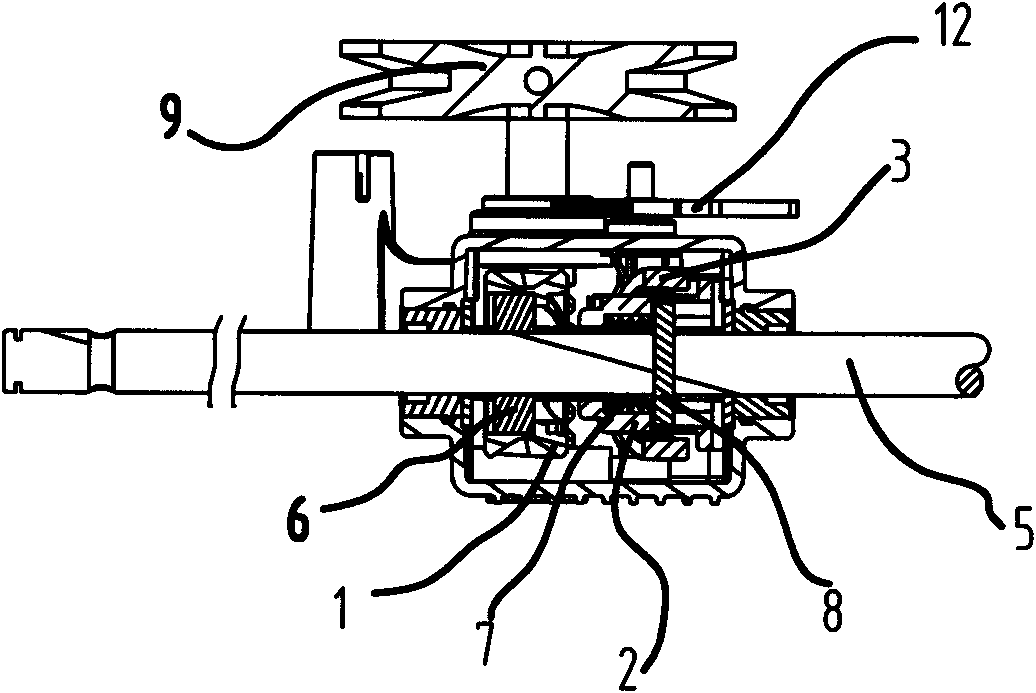
[0013] Such as Figure 1b , Figure 2b with Figure 3a As shown, the pulley 9 is fixedly connected to the end of the power input shaft, the power output shaft 5 passes through the inner cavity of the worm wheel 1 and is rotatably fixed by the bearing 6, and the power output shaft 5 enters the inner cavity of the shaft sliding sleeve 2, and is arranged on the shaft The positioning pin 8 on the inner wall of the sliding sleeve 2 passes through the power output shaft 5 vertical...


PUM


Abstract

The invention relates to an end face tooth engaged and separated structure for a speed reducer of a mowing machine. The engaged and separated structure comprises a worm wheel, a power input worm rod externally engaged with the worm wheel, a power output shaft arranged in the worm wheel and a pull and control operation component arranged at one side of the worm rod; one end face of the worm wheel is internally provided with an end face tooth and a shaft sliding sleeve sleeved outside the power output shaft; one end face of the shaft sliding sleeve is externally provided with an end face tooth correspondingly engaged with the end face tooth arranged in one end face of the worm wheel; the other end face of the shaft sliding sleeve is provided with a locating pin tightly fixed with the power output shaft; a compression spring is arranged between the inner wall of the end face tooth of the shaft sliding sleeve and the locating pin; and the outer peripheral wall of the shaft sliding sleeve is provided with a shift fork which enables the shaft sliding sleeve to axially slide. In the engaged and separated structure, bevel friction is replaced by end face gear engaging force, so that the dynamics and the speed of jointing or separation are improved to make operation convenient and control flexible and prevent the damage of bevel friction; the service life of the end face tooth engaged structure is doubled compared with that of a friction cone structure; and the climbing speed and the mowing efficiency are obviously improved under the same condition.

Description

technical field [0001] The invention relates to a running mechanism of a lawn mower, in particular to a running mechanism for a lawn mower with a speed reducer clutch output power. Background technique [0002] Lawn mowers used in places such as urban green belts generally use worm gear reducers to achieve the purpose of small size, light weight, and durability, especially the use of worm gear reducers to output drive travel mechanisms has been widely used. The drive reduction box for grass machine, because the linkage device of the worm gear reducer is fixed on the power output shaft of the running mechanism in the circumferential direction by the friction cone, the engagement and separation are realized by the axial friction force, and the friction force depends on the curved dial. The rod exerts pressure on the friction cone to achieve it, so it usually needs to maintain enough maintaining force to work effectively. The operator is very laborious and difficult to master. ...

Claims


Application Information

Patent Timeline
IPC IPC(8): A01D69/08
Inventor 徐毅
Owner YUYAO SOBO GARDEN MACHINERY
Why Eureka
Try Eureka