Eureka AIR delivers breakthrough ideas for toughest innovation challenges, trusted by R&D personnel around the world.

Deformable reflecting membrane for reconfigurable reflector and antenna having the same

A technology of reflectors and diaphragms, applied in the field of space applications, can solve problems such as flexural stiffness and low thermal expansion coefficient

Inactive Publication Date: 2011-08-31
THALES SA
View PDF5 Cites 2 Cited by
  • Summary
  • Abstract
  • Description
  • Claims
  • Application Information

AI Technical Summary

Problems solved by technology

[0008] The object of the present invention is to overcome the drawbacks of known deformable reflective surfaces and to produce deformable reflective membranes with high radio-frequency reflectivity, which membranes have highly elastic regions enabling multiple directions in and out of the plane of the membrane's surface can be significantly deformed; exhibit flexural stiffness and low thermal expansion coefficient, which makes the separator dimensionally stable in the temperature range corresponding to space applications; and have good electrical uniformity or electrical contact with each other Insulation, so as not to generate very high levels of intermodulation products

Method used


Image

  • Deformable reflecting membrane for reconfigurable reflector and antenna having the same
  • Deformable reflecting membrane for reconfigurable reflector and antenna having the same
  • Deformable reflecting membrane for reconfigurable reflector and antenna having the same

Examples


Embodiment Construction

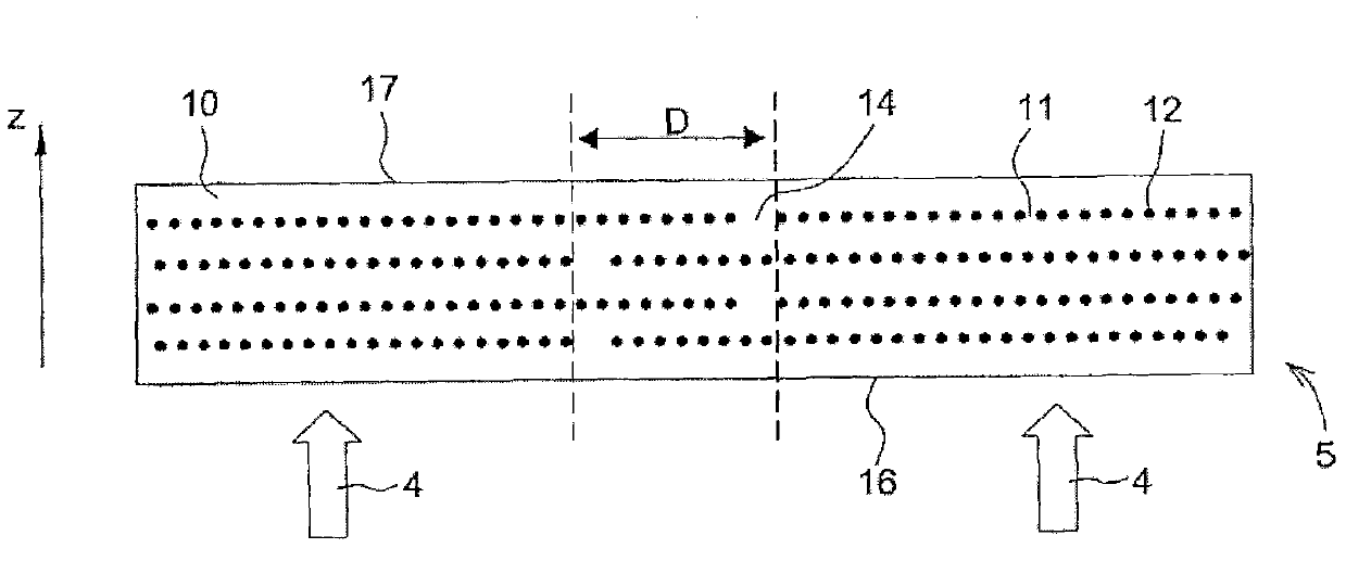
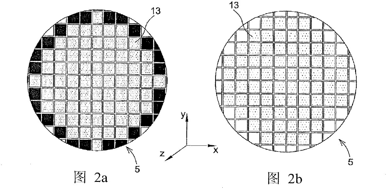
[0023] figure 1 The shown membrane part 5 comprises, in the thickness direction along the Z axis, alternately superimposed layers of conductive elastomer 10 and a reinforcement layer 11 which is non-uniform in the XY plane of the layer. The reinforcement layer 11 is discontinuous and comprises individual fragments 13 spatially separated from each other and arranged periodically in the plane of the membrane. Fragments 13 may for example consist of a grid of discontinuous wires forming fabrics comprising hard wires 12 having a very high Young's modulus greater than 100 GPa and having a very short The elastic region, for example, has an elongation of the order of 0.2% (the percent elongation of an elastic material corresponds to the ratio of its ability to extend to its length). The wire 12 is preferably composed of a material having a low coefficient of thermal expansion below 10 ppm / °C, such as carbon fibers, or fibers composed of an iron-nickel alloy such as Invar (registered...


PUM


Abstract

The invention provides a deformable reflecting membrane for a reconfigurable reflector and an antenna having the same. The deformable reflecting membrane (5) comprises a conductive elastomer layer (10) and at least two reinforcing layer (11) which are intermeshed in a thickness direction. Each reinforcing layer is divided in a manner of being separated from each other in terms of space. Independent fragments are disposed on the plane of the membrane in a periodical manner. The invention is especially suitable for space area.

Description

technical field [0001] The present invention relates to deformable reflective membranes for reconfigurable reflectors, reconfigurable reflectors comprising such membranes and antennas comprising such reflectors. It applies to any antenna reflector that requires modification of the beam shape in use, and more particularly to space applications such as satellite radiocommunications. Background technique [0002] One existing method of obtaining a beam with a shaped profile includes using multiple illumination feeds according to appropriate illumination rules, using single or double off-center reflector systems, or even using multiple direct radiation feeds. The radiating element at the feed end is excited by a signal whose phase and amplitude are optimized by a beam forming network (BFN) comprising a plurality of waveguides. However, such antennas, known as array antennas, are very complex, exhibit radio frequency energy losses, and have a considerable weight, which hinders t...

Claims


Application Information

Patent Timeline
Patent Type & Authority Applications(China)
IPC IPC(8): H01Q15/14H01Q19/10
CPCH01Q15/147
Inventor L·施莱德S·德佩尔V·贝勒伊P·勒佩尔捷J-P·泰桑
Owner THALES SA
Why Eureka
Eureka Blog
Learn More