
Inlet guide plate with guide wheel for strip steel rolling, coiling and finishing equipment

A guide wheel and strip steel technology, which is applied in coiling and finishing, and strip steel rolling, can solve the problems of poor coil shape in the next process, difficult coiling, and scrap steel coiling, etc., to improve edge quality , Improve the effect of introduction and service life improvement

Inactive Publication Date: 2011-08-31
BAOSHAN IRON & STEEL CO LTD
View PDF6 Cites 2 Cited by
  • Summary
  • Abstract
  • Description
  • Claims
  • Application Information

AI Technical Summary

Problems solved by technology

[0007] However, when the thin strip is transported at high speed, the slightly upturned head is more likely to produce a larger warped head, which makes it difficult to be involved in coiling and scrap steel
Since the vertical guide wheel has no relative speed with the strip in the vertical direction when it rotates, it has no downward effect on the strip traveling at high speed, and eventually the strip will often be driven by the strip head when it is fed into the finishing mill and coiler. The part is upturned and the scrap or coiling fails
[0008] In addition, when the strip steel is in contact with the vertical guide plate, burrs will be formed on the edge of the strip steel, and the edge trimming burrs of 0.01-0.5 mm on the edge of the strip steel cannot be avoided during the strip edge trimming process. The existence of these burrs will Causes poor roll shape in the next process
There is no effective solution to these problems in the current hot-rolled strip production

Method used


Image

  • Inlet guide plate with guide wheel for strip steel rolling, coiling and finishing equipment
  • Inlet guide plate with guide wheel for strip steel rolling, coiling and finishing equipment
  • Inlet guide plate with guide wheel for strip steel rolling, coiling and finishing equipment

Examples


Embodiment 1

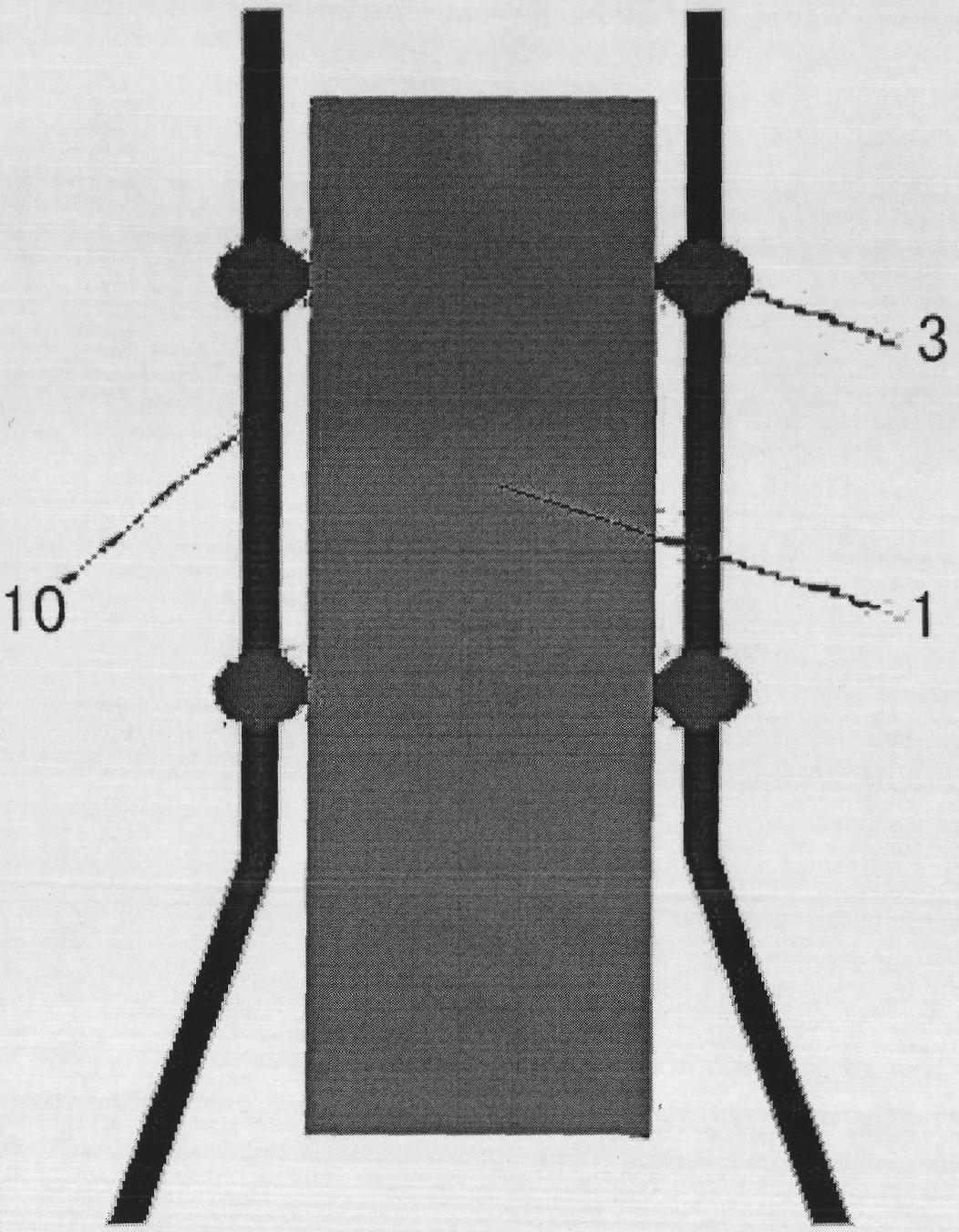
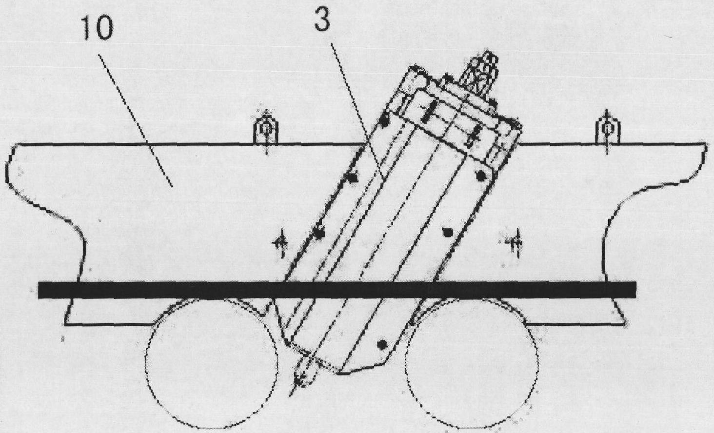
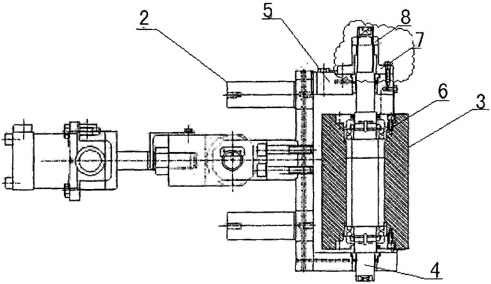
[0031] An entrance guide plate with guide wheels for strip steel rolling, coiling and finishing equipment, comprising guiding strip steel 1 running, guide plates 10 arranged on both sides of the strip steel 1 and guide wheels 3 arranged on the guide plate. The guide wheel is arranged obliquely relative to the guide plate, that is, the direction of the circumferential speed of the guide wheel and the advancing direction of the steel strip 1 have an included angle α of 0-30 degrees. Reach not only preventing strip steel 1 from warping but also avoid overcorrecting and causing buckle.

[0032] Due to the inclined arrangement of the guide wheel, its downward sub-velocity (Vy) can suppress the strip steel 1, so that the strip steel 1 can be transported stably and the head is tilted, and at the same time, it has a certain grinding effect on the edge of the strip steel 1.

[0033] In this embodiment, the height of the guide wheel body can be adjusted to change the contact position be...


PUM


Abstract

The invention discloses an inlet guide plate with a guide wheel for strip steel rolling, coiling and finishing equipment. The inlet guide plate comprises guide plates (10) arranged at both sides of strip steel (1) and used for guiding the operation of the strip steel (1), and guide wheels (3) arranged on the guide plates. The guide wheels (3) are inclined relative to the guide plates (10), namely an included angle (a) of 0-30 DEG is formed between a direction of a circumferential speed of the guide wheels and a forward direction of the strip steel (1). Each guide wheel (3) can move along an axis direction thereof, and a height of the guide wheel can be adjusted. Because the contact of the inclined guide wheels (3) and the strip steel (1) is changed from circumference to ellipse, the linear contact becomes longer, so that a rotating speed of the guide wheels (3) is reduced as compared to a vertical manner, thus the service life of the guide wheels (3) is greatly prolonged, the strip steel (1) is prevented from warping, and leading-in of the strip steel (1) is improved; meanwhile, because a downward component velocity has certain grinding effect on the side part of the strip steel (1), the quality of the side part of the strip steel (1) is improved, and the yield of the strip steel (1) is improved.

Description

technical field [0001] The invention relates to the field of steel strip rolling, coiling and finishing, in particular, the invention relates to an inlet guide plate with guide wheels for strip rolling, coiling and finishing equipment. Background technique [0002] Entrance guide plates are widely used in hot rolling and continuous rolling production line equipment (such as finishing rolling mills, roughing mills and coilers, etc.) of domestic and foreign iron and steel enterprises to ensure the alignment of the strip steel and prevent the strip steel from moving during the process , Improve the introduction and forming of strip steel. [0003] Guide plates are widely used at the entrance of rolling mills and coilers for the introduction and deviation correction of strip steel. The guide plate is inevitably worn during the process of guiding and correcting the strip steel, because the travel height of the strip steel is generally at the height of the rolling line. For this...

Claims


Application Information

Patent Timeline
Patent Type & Authority Applications(China)
IPC IPC(8): B21B39/14B21C47/34
Inventor 师好智江光彪顾晓明
Owner BAOSHAN IRON & STEEL CO LTD
Learn More