
Improvements in ocean wave energy extraction

An energy extraction, ocean wave technology, applied in ocean energy power generation, machines/engines, hydroelectric power stations, etc., can solve the problems of high cost, large size, and the system cannot survive commercially.

Active Publication Date: 2011-08-24
HAIKONA NEW ENERGY CO LTD
View PDF6 Cites 7 Cited by
  • Summary
  • Abstract
  • Description
  • Claims
  • Application Information

AI Technical Summary

Problems solved by technology

It has been found that these additional costs are often so high that they may render the system commercially unviable
[0009] Systems built to withstand maximum extreme forces are necessarily larger in size, thus reducing the visual appeal of these systems

Method used


Image

  • Improvements in ocean wave energy extraction
  • Improvements in ocean wave energy extraction
  • Improvements in ocean wave energy extraction

Examples


Embodiment Construction

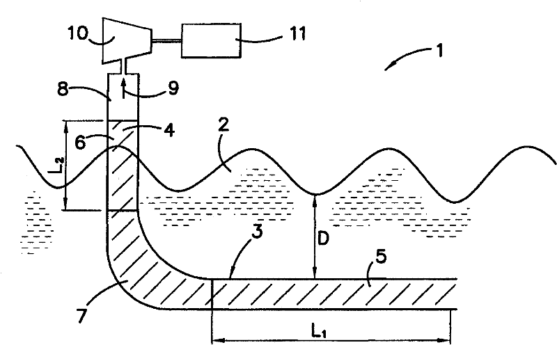
[0075] Referring to the figures, an ocean wave energy extraction system 1 is located in a body of water such as an ocean 2 . The wave energy extraction system 1 includes a pipeline 3 that receives seawater to form a water column 4 . As will be described in more detail below, the water column 4 oscillates within the conduit 3 in response to the rise and fall of the waves passing through the wave energy extraction system 1 .

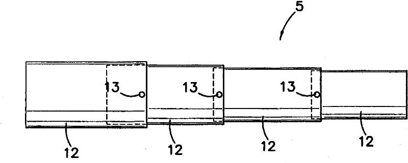
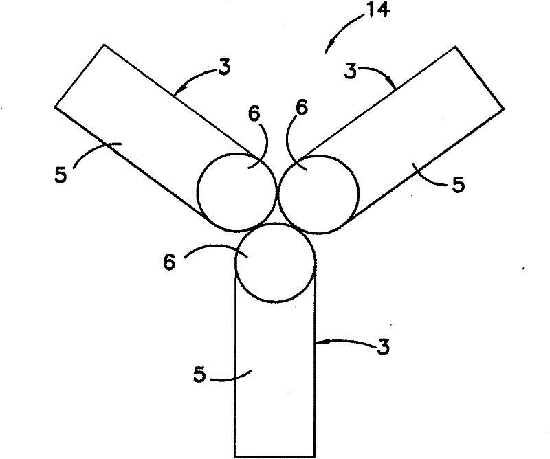
[0076] The conduit 3 has a first section 5, a second section 6 arranged transverse to the first section, and a flow control section 7 between the first and second sections. like figure 1 As shown, the conduit 3 is substantially L-shaped and is configured such that the first section 5, the second section 6 and the flow control section 7 form an integral unit. The segments of the duct 3 are open at their ends to form continuous through holes along the duct. In the embodiment shown in the figures, the bore of the conduit has a circular cross-sectional area...


PUM


Abstract

An improved ocean wave energy extraction system is disclosed. The system includes at least one duct for receiving an oscillating water column. The duct has a first segment, a second segment arranged transversely to the first segment and a flow control segment intermediate the first and second segments. The flow control segment is configured to inhibit turbulent flow of the oscillating water column flowing within the duct. A turbine is in fluid communication with the second segment of the duct such that the turbine is driven by the fluid flow which is generated by the oscillations of the oscillating water column within the duct. The turbine rotates an electric generator to thereby generate electrical energy.

Description

technical field [0001] The present invention relates to sustainable energy production. More particularly, the present invention relates to improvements in ocean wave energy extraction, and to systems and methods of ocean wave energy extraction. Background technique [0002] Any discussion of the prior art throughout this specification should in no way be considered as being known or forming part of the common general knowledge in the field. [0003] Environmental concerns and awareness of the limited resources of traditional combustible hydrocarbon fuel sources have led to research into sustainable non-polluting energy sources such as wave, wind, tidal, geothermal and solar. [0004] Many different types of wave power systems have been proposed. The basic principle employed by one system is to use the vertical motion inherent in wave motion to achieve the rotational motion of the turbine to directly or indirectly drive a generator to generate electricity. In such systems,...

Claims


Application Information

Patent Timeline
Patent Type & Authority Applications(China)
IPC IPC(8): F03B13/24F03B13/10F03B13/14E02B9/08
CPCY02E10/38E02B9/08F03B13/24F03B13/142F05B2240/40Y02E10/32Y02E10/30
Inventor T·丹尼斯S·亨特
Owner HAIKONA NEW ENERGY CO LTD
Learn More