
Clamping spring structure of relay socket

A technology of relay socket and clip spring, which is applied in the field of structural improvement of the input port, can solve the problems of increasing difficulty, affecting the insertion of the relay, and the easy damage of the plastic partition wall 12', so as to improve the withstand voltage, facilitate the use, increase the The effect of width

Inactive Publication Date: 2011-08-24
XIAMEN HONGYUANDA ELECTRIC APPLIANCE
View PDF7 Cites 13 Cited by
  • Summary
  • Abstract
  • Description
  • Claims
  • Application Information

AI Technical Summary

Problems solved by technology

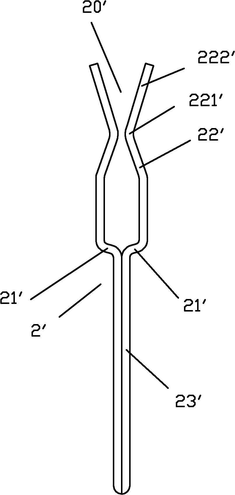
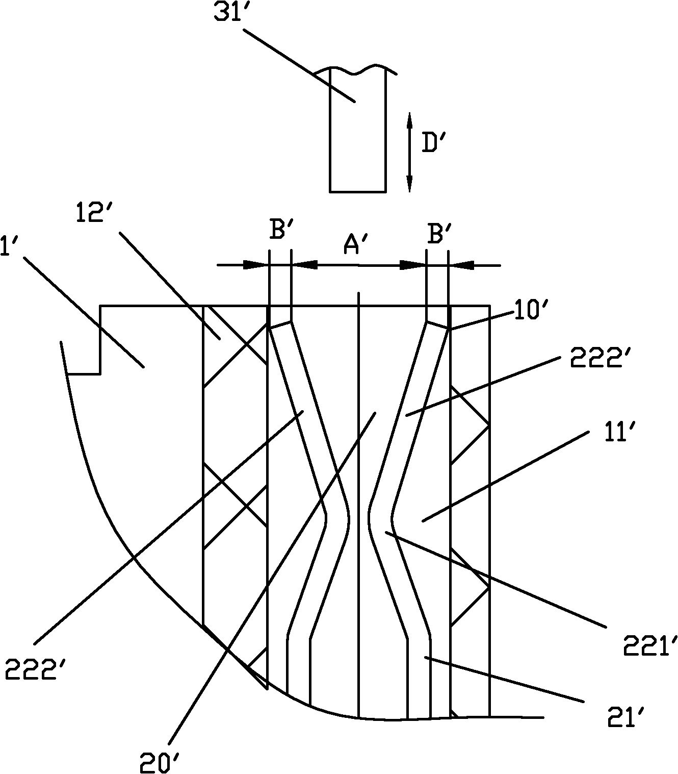
In this way, this cross section occupies a certain space B' in the insertion direction of the relay pin 31', making the width A' of the V-shaped mouth of the input port 20' smaller, and increasing the relay pin 31' to be inserted into the clamp spring input port. 20' difficulty, especially when the lower end face of the relay lead pin 31' touches the end face of the end 222' of the free end 22', it will affect the insertion of the relay lead pin 31'; in addition, the free end 22' of the reed The end 222' of the reed is close to the side of the insulating wall, and there is an acute angle, which makes the contact between the end 222' of the free end 22' of the reed and the wall of the plastic partition wall 12' be a line surface in normal use of the relay socket. Contacting 10' will make the plastic partition wall 12' easily damaged, reducing the withstand voltage, insulation performance and life of the relay socket

Method used


Image

  • Clamping spring structure of relay socket
  • Clamping spring structure of relay socket
  • Clamping spring structure of relay socket

Examples


Embodiment Construction

[0020] Examples, see Figure 6 to Figure 7 As shown, the clip spring structure of a kind of relay socket of the present invention, this clip spring 2 is made of two reeds 21 of strip-shaped alloy copper; Each end of two reeds 21 is set as free end 22, two reeds Each other end of 21 is connected as a whole to form opposite fixed end 23; A bending portion 221 is respectively provided in the middle part of the free ends of two leaf reeds 21, and this bending portion 221 just makes the end 222 of the free end of two leaf reeds form a V-shaped as the input port 20; when the relay lead pin is inserted, the input port 20 of the clip spring 2 can maintain a certain pressure on it. A chamfered surface 223 is respectively provided at the ends 222 of the free ends of the two reeds, and the chamfered surface 223 is arranged vertically.

[0021] see Figure 5 to Figure 9 As shown, a kind of relay socket of the present invention comprises a base 1 and a clip spring 2; a slot 11 for instal...


PUM


Abstract

The invention discloses a clamping spring structure of a relay socket. The clamping spring structure consists of two reeds made of banded cooper alloy; one end of each reed is a free end and the other ends of the two reeds are connected together to form opposite fixed ends; the middle parts of the free ends of the two reeds are respectively provided with a bending part; a V shape serving as an input port is formed by tail ends of the free ends of the two reeds through the bending parts; and end heads of the tail ends of the free ends of the two reeds are respectively provided with a chamfering surface arranged vertically. By improvement on the input port of the clamping spring structure, the width of the input port of a clamping spring is increased so as to facilitate the insertion of leading feet of a relay into the input port of the clamping spring; a line-to-surface contact between the tail ends of the free ends of the reeds and the surface of a plastic partition wall is changed into a surface-to-surface contact to make the application of the relay socket more convenient; and the insulating wall is difficult to damage so that the performance of voltage withstand and insulation of the relay socket are improved and the service life of the relay socket is prolonged.

Description

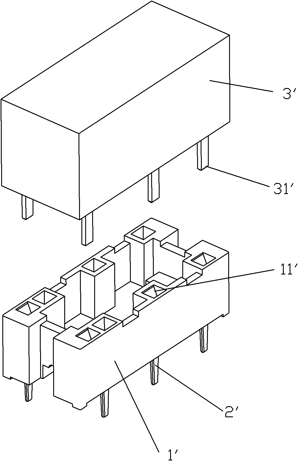
technical field [0001] The invention relates to a relay socket, in particular to a structural improvement of an input port of a clamp spring structure of a relay socket. Background technique [0002] Relay socket, as a low-voltage connector, is widely used in various industrial control equipment. Existing relay sockets such as figure 1 As shown, it generally consists of base 1', clip spring 2', cover plate, protection circuit and other components. The clip spring 2' is usually installed in the base 1', and the base 1' is provided with a slot 11' for installing the clip spring 2'. The slot 11' is actually surrounded by the plastic partition wall 12' of the base. In this way, the clip spring 2' can be separated from other clip springs or conductive parts by the plastic partition wall 12' of the base as an insulating wall to meet a certain electrical insulation performance. [0003] Clip spring 2 ' is an important part in the relay socket, and the clip spring 2 ' of existing...

Claims


Application Information

Patent Timeline
IPC IPC(8): H01R33/76H01R13/115
Inventor 薛春芳
Owner XIAMEN HONGYUANDA ELECTRIC APPLIANCE
Learn More