Actuator cylinder of built-in buffer load-reducing device

An actuating cylinder and load reduction technology, applied in the direction of fluid pressure actuating devices, etc., can solve the problems of fatigue damage, inability to adapt, and high temperature of the system oil, so as to reduce the process difficulty and manufacturing and use costs, avoid collisions and The effect of overload extrusion and improving performance stability

Active Publication Date: 2011-08-24
LANDING GEAR ADVANCED MFG
View PDF7 Cites 6 Cited by
  • Summary
  • Abstract
  • Description
  • Claims
  • Application Information

AI Technical Summary

Problems solved by technology

When the piston rod returns, in order to ensure that the starting speed of the piston is not affected by the throttling device of the buffer mechanism, it is necessary to set a return fast oil supply valve in the buffer load reduction device, which makes the structure of the actuator complicated and complicated; the throttling and buffering effect is affected. Parts manufacturing errors, oil temperature (i.e. viscosity), piston movement speed and other conditions have a great influence and are unstable; at the moment of buffering, a large pulse pressure is formed in the buffer chamber, which will generate pulse vibration to the hydraulic system. At the same time, throttling buffer It is easy to cause the system oil temperature to rise too quickly; during the buffer period and immediately before the end of the actuator piston rod movement, the output force of the actuator does not decrease, which will cause instantaneous overload extrusion on the moving mechanism or parts, and repeat for a certain number of times After the overload extrusion, the parts of the moving mechanism and actuator gradually produce fatigue damage
[0003] With the development of modern technology, the requirements for hydraulic actuators are simple and compact in structure, complete in functions, reliable in quality, stable in performance, long in life, easy to maintain, and low in manufacturing and use costs. Therefore, the traditional throttling and buffering actuators It has gradually failed to adapt to the development of modern technology, especially modern aircraft and warship technology

Method used


Image

  • Actuator cylinder of built-in buffer load-reducing device
  • Actuator cylinder of built-in buffer load-reducing device
  • Actuator cylinder of built-in buffer load-reducing device

Examples


Embodiment Construction

[0031] The present invention will be further elaborated below in conjunction with the accompanying drawings and embodiments.

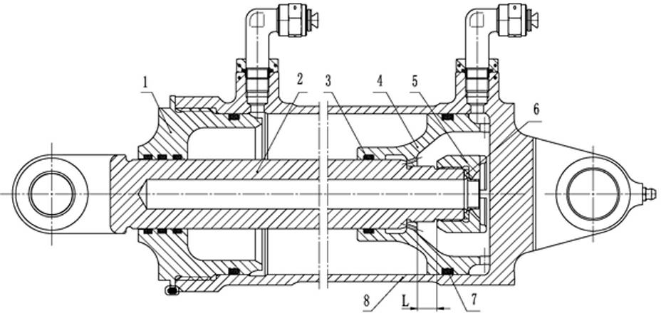
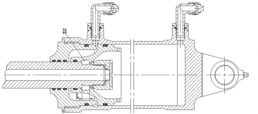
[0032] A cylinder with a built-in buffer and load reduction device, such as figure 1 , figure 2 , image 3 As shown, it includes a cylinder head 1, a cylinder body 8, a piston 4, a piston rod 2, a lock nut 5, and a self-locking retaining ring 6. Such as Figure 4 As shown, the piston rod 2 is provided with a stepped optical axis 9 , a threaded shaft 10 , and a stepped large axis end face 11 . Such as Figure 5 As shown, the inner hole at one end of the piston 4 is provided with a stepped hole 12 and a piston stepped small hole end face 19, an annular groove 13 is provided between the stepped holes 12, a sealing groove 14 is provided in the large stepped hole, and the other end of the piston is provided with The inner groove 20 and the groove end surface 17, the inner groove 20 communicates with the stepped hole 12, a plurality of evenly distribut...


PUM


Abstract

The invention discloses an actuator cylinder of a built-in buffer load-reducing device, belonging to the field of aviation hydraulic actuator cylinders, for solving the problem of unobvious pure throttling buffer effect of the existing actuator cylinder. The actuator cylinder comprises a cylinder cover, a cylinder body, a piston rod and a piston, wherein the piston rod penetrates through the cylinder cover; the piston is arranged in the cylinder body, and is connected with the cylinder body through a locking nut; and a floating clearance which can move relative to the piston rod is arranged between a great ladder shaft end surface of the piston rod and the locking nut. According to the invention, a rapid return starting function can be kept without arranging a special return rapid oil supplying valve, simultaneously two tail ends of the actuator cylinder have buffer functions, moreover the loading output by the actuator cylinder is reduced in the buffer process, the collision and overloading extrusion of parts of the actuator cylinder or a moving mechanism are avoided, the structure of the actuator cylinder is simplified and compacted, and technology difficulty and manufacturing and using cost for manufacturing and assembly are reduced, and the stability and safety reliability are improved.

Description

technical field [0001] The invention relates to the field of aviation hydraulic actuators, in particular to a hydraulic actuator with a built-in buffer and load reduction device. Background technique [0002] The working principle of the traditional actuator buffer load reduction device is: when the actuator piston moves to the end of the stroke, a certain volume of liquid is sealed in the low-pressure chamber through the buffer mechanism, and then squeezed out through the orifice in the throttling device. As a result, the volume change per unit time in the actuator decreases, causing back pressure, thereby reducing the relative movement speed of the piston rod and the cylinder, and converting kinetic energy into heat energy. When the piston rod returns, in order to ensure that the starting speed of the piston is not affected by the throttling device of the buffer mechanism, it is necessary to set a return fast oil supply valve in the buffer load reduction device, which make...

Claims


Application Information

Patent Timeline
Patent Type & Authority Applications(China)
IPC IPC(8): F15B15/22
Inventor 邓晓山黄立新金军汪赵宏王保相张万民
Owner LANDING GEAR ADVANCED MFG
Why Eureka
Try Eureka