
Parking brake system

A braking device and parking technology, applied in the direction of braking transmission, brakes, braking components, etc., can solve problems such as high working cost and achieve the effect of improving safety

Inactive Publication Date: 2011-08-17
KNORR BREMSE SYST FUER NUTZFAHRZEUGE GMBH
View PDF6 Cites 16 Cited by
  • Summary
  • Abstract
  • Description
  • Claims
  • Application Information

AI Technical Summary

Problems solved by technology

[0003] A disadvantage of such a high level of integration of the compressed air treatment unit with the parking brake module is the high work costs for repairs after damage has occurred

Method used


Image

  • Parking brake system
  • Parking brake system
  • Parking brake system

Examples


Embodiment Construction

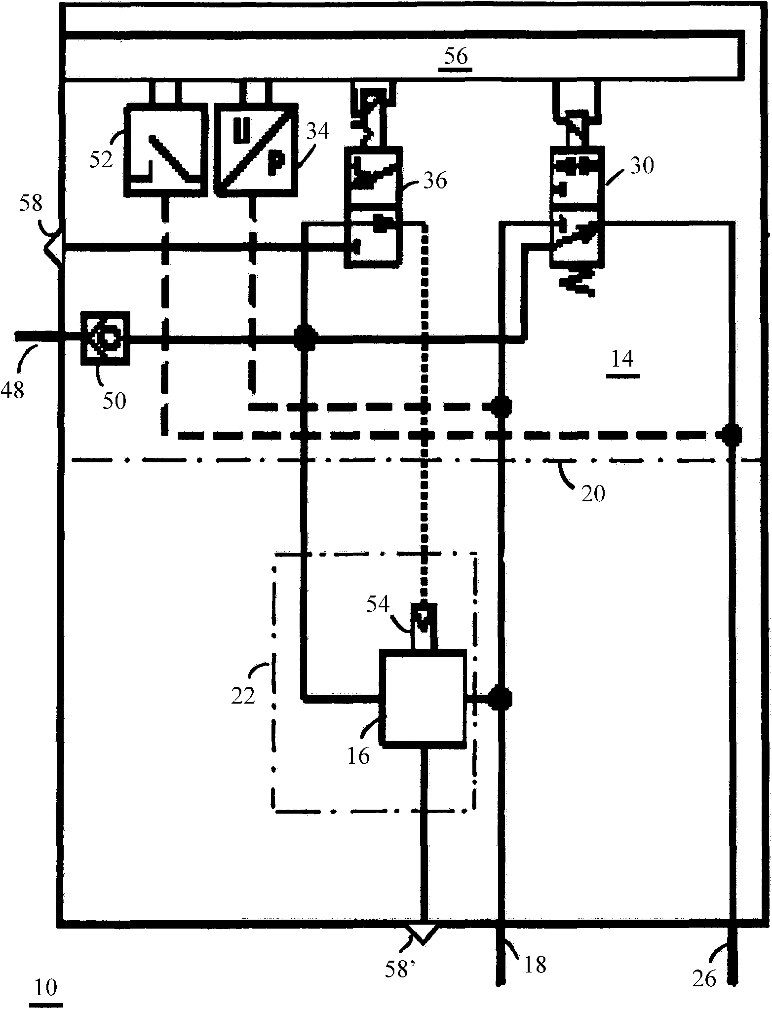
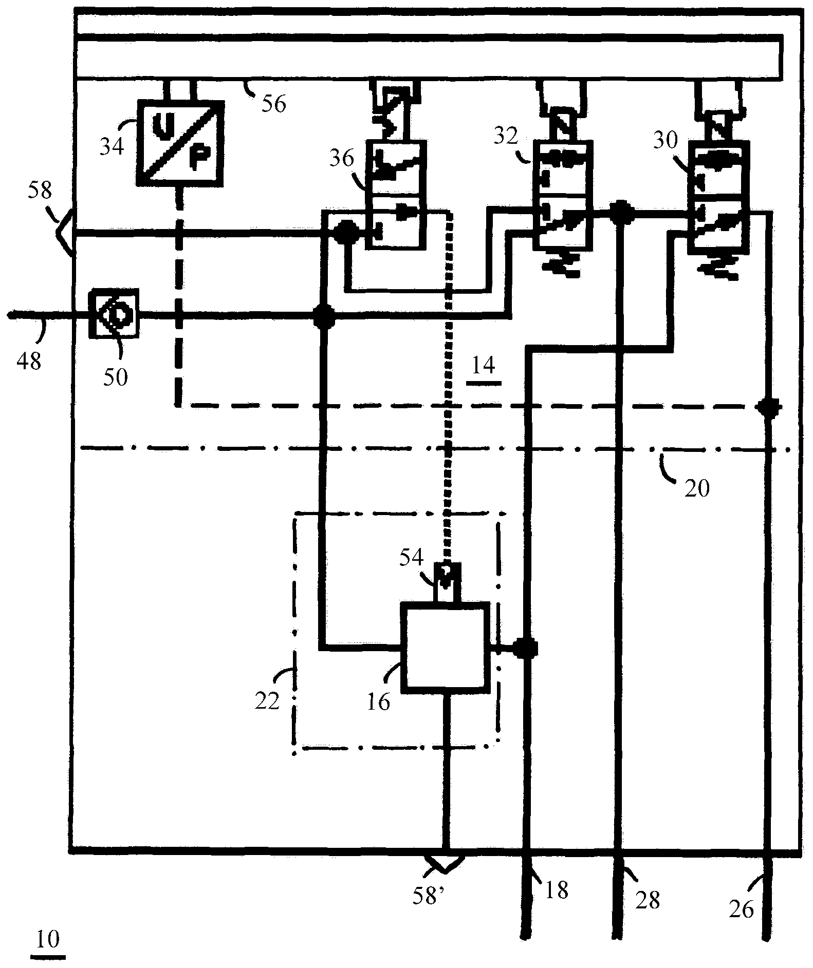
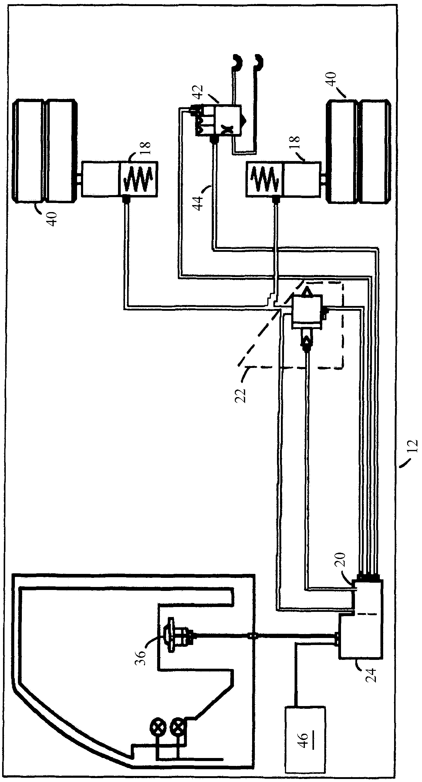
[0018] figure 1 A first embodiment of the parking brake device is shown. The illustrated parking brake device 10 is subdivided into a first module 20 and a second module 22 arranged at a distance from the first module 20 . The first module 20 comprises the valve arrangement 14 and the controller 56 , while the relay valve 16 is arranged in the second module 22 . The relay valve 16 arranged in the second module 22 is connected via a pressure line to the valve device 14 arranged in the first module 20 , wherein a supply pressure can be delivered via the line. The bistable solenoid valve 36 downstream of the check valve 50 , which is part of the valve arrangement 14 , is supplied with supply pressure via the pressure supply device 48 . The bistable solenoid valve 36 can be controlled by a controller 56 and acts on the control input 54 of the relay valve 16 with supply pressure in its shown switching position. The spring-loaded brake cylinder 18 , which is connected downstream ...


PUM


Abstract

The invention relates to a parking brake system (10) for a vehicle (12), comprising an at least partially bistable valve unit (14) to generate a control pressure for controlling at least one function of the parking brake system (10), and a relay valve (16) which receives the control pressure from the valve unit (14) and either pressurizes or bleeds at least one spring-loaded cylinder (18) according to the control pressure. According to the invention, the valve unit (24) is integrated into a first module (20) integrated into a compressed air production system (24), and the relay valve (16) is arranged in a second module (22) which is arranged at a distance from the first module (20) and the compressed air production system (24).

Description

technical field [0001] The invention relates to a parking brake system for a vehicle having an at least partially bistable valve for generating a control pressure for pilot control of at least one function of the parking brake system device; and a relay valve which receives the control pressure of the valve device and charges or degasses at least one spring accumulator cylinder depending on the control pressure. Background technique [0002] Parking brakes of this type are widely used in particular in the commercial vehicle sector, in which a compressed air-operated parking brake is often provided as a supplement to a compressed air operated service brake. Such parking brake devices generally comprise: a valve arrangement, which may comprise a plurality of individual valves, for example electrically operable and which may generate different control pressures; The accumulator cylinder is inflated or exhausted. In order to simplify the assembly of all components, all compone...

Claims


Application Information

Patent Timeline
Patent Type & Authority Applications(China)
IPC IPC(8): B60T13/68B60T17/04
CPCB60T17/02B60T13/38B60T13/683B60T17/04B60T15/18
Inventor 爱德华·希尔贝雷尔迈克尔·赫格斯彼得·塞莱
Owner KNORR BREMSE SYST FUER NUTZFAHRZEUGE GMBH
Learn More