Eureka AIR delivers breakthrough ideas for toughest innovation challenges, trusted by R&D personnel around the world.

Method of designing tire and tire

A design method and tire technology, applied in the direction of tire tread/tread pattern, tire parts, transportation and packaging, etc., can solve the problems of loss of performance, affecting the freedom of tread pattern design, etc., and achieve the effect of reducing tire noise

Inactive Publication Date: 2011-08-17
BRIDGESTONE CORP
View PDF8 Cites 6 Cited by
  • Summary
  • Abstract
  • Description
  • Claims
  • Application Information

AI Technical Summary

Problems solved by technology

That is, the method of forming a wide circumferential groove in the center of the tread and the method of forming the circumferential length of the block irregularly affect the degree of freedom in the design of the tread pattern.
Therefore, if a unique tread pattern is adopted in order to reduce air column tube resonance noise and pitch noise, other performances required for tires such as performance on wet roads will be lost.

Method used


Image

  • Method of designing tire and tire
  • Method of designing tire and tire
  • Method of designing tire and tire

Examples


Embodiment Construction

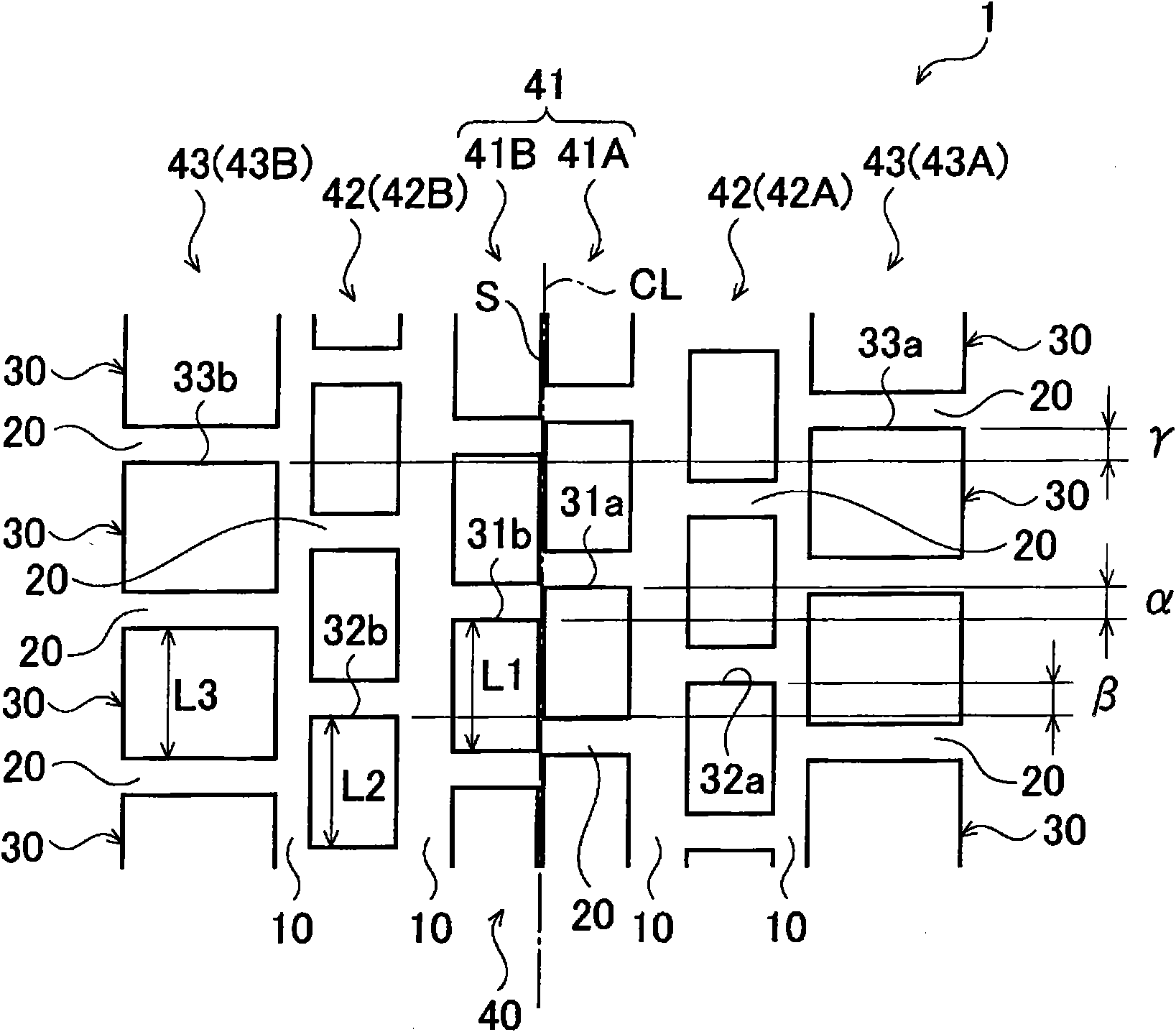
[0031] Next, an embodiment of a tire design method and a tire (pneumatic tire) according to the present invention will be described with reference to the drawings. In detail, (1) structure of a pneumatic tire, (2) tire design method, (3) operation and effect, (4) comparative evaluation, and (5) other embodiments will be described.

[0032] In addition, in the following drawings, the same or similar code|symbol is attached|subjected to the same or similar part. However, the drawings are schematic diagrams, and it should be noted that the ratio of each dimension is different from the real thing.

[0033] Therefore, specific dimensions and the like must be judged with reference to the following description. In addition, it is needless to say that there are parts in which the dimensional relationship is different and the ratio is different between the respective drawings.

[0034] (1) Structure of pneumatic tire

[0035] First, the configuration of a pneumatic tire 1 according ...


PUM


Abstract

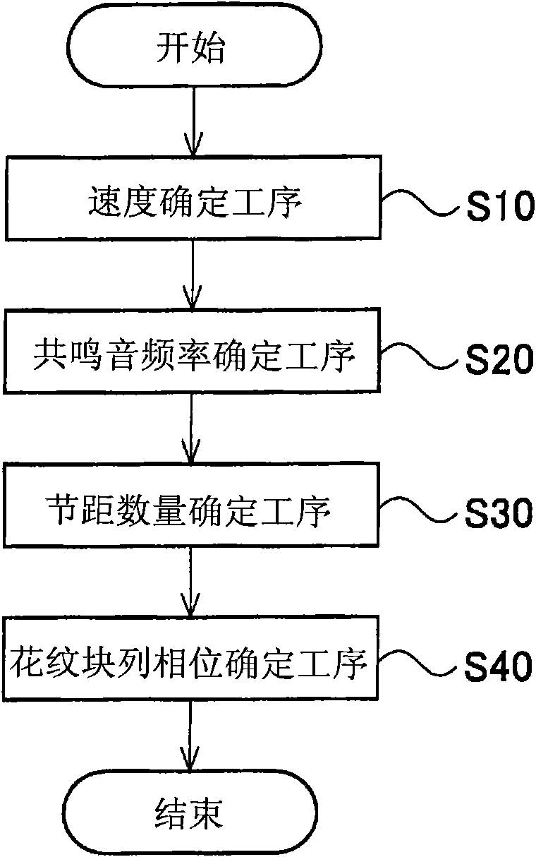
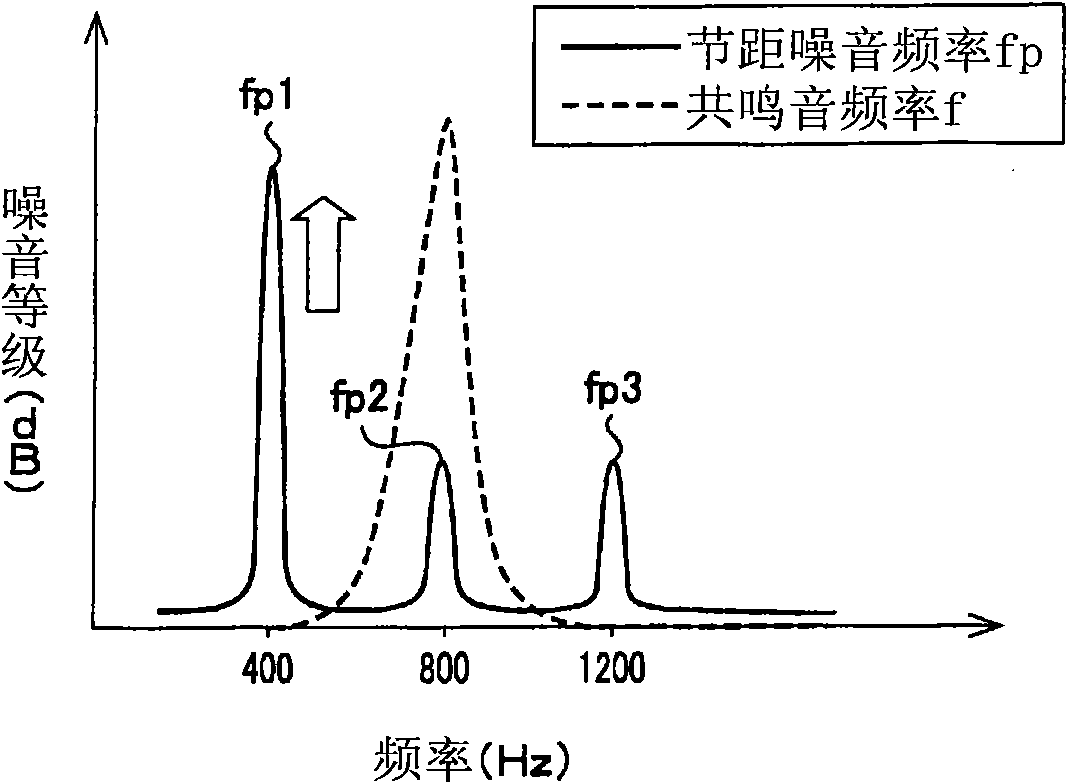
The invention provides a method of designing tires and the tires. The method of designing a tire comprises a step (20) for determining a resonance frequency (f) which is generated from the tire based on the ground contact length of the tire when a regular internal pressure and a regular load are applied to the tire, a step (30) for determining the number of pitches of a block row, and a step (40) for determining the phase of the block row which is defined by the interval of arrangement between a plurality of blocks constituting the block row when the band of secondary pitch noise frequency (fp2) caused by the block row at the reference speed, i.e. the reference traveling speed of a vehicle to which the tire is attached, overlaps the band of the resonance frequency (f). At step (40), the phase of a block row is determined such that there is a 10-30% deviation between a block row and a second block row with respect to the equator line of the tire.

Description

technical field [0001] The present invention relates to a design method of a tire and a tire having a block row formed along the tire circumferential direction, which is composed of a plurality of blocks divided by circumferential grooves and lateral grooves. Background technique [0002] The main causes of tire noise, which is the noise generated by the tire rolling on the road surface, include the air column resonance sound generated by the air column tube formed by the road surface and the circumferential groove such as the main groove extending along the tire circumferential direction, Pattern vibration noise (pitch noise) caused by the impact of the tread formed with lateral grooves on the road surface. [0003] Conventionally, as a method of reducing air columnar tube resonance noise, a method of forming a wide circumferential groove in the center of the tread is known (for example, Patent Document 1). [0004] Also, as a method of reducing pitch noise, a method of ma...

Claims


Application Information

Patent Timeline
Patent Type & Authority Applications(China)
IPC IPC(8): B60C19/00B60C11/03
CPCB60C11/11B60C11/0318B60C99/006
Inventor 樱庭一树
Owner BRIDGESTONE CORP
Why Eureka
Eureka Blog
Learn More