
Multifunctional arc welding vision monitoring device and monitoring method

A monitoring device and multi-functional technology, applied in the direction of arc welding equipment, welding equipment, manufacturing tools, etc., can solve the problems of increased number of equipment, high cost, high multiple target areas, etc., and achieve simple and easy operation, simple and compact structure , the effect of convenient operation

Inactive Publication Date: 2011-08-17
TANGSHAN KAIYUAN WELDING AUTOMATION TECH INST
View PDF9 Cites 3 Cited by
  • Summary
  • Abstract
  • Description
  • Claims
  • Application Information

AI Technical Summary

Problems solved by technology

The system as a whole has no dust protection and cooling protection devices, especially during the welding process, only the arc or molten pool shape can be monitored through the filter, and only the arc area is visible in the monitoring screen, and the electrodes and The relative position of the weld seam, the surrounding environment of the welding area and the shape of the weld seam
To achieve visibility in other areas, using the structural characteristics of the original product, it is necessary to add multiple sets of equipment such as laser lighting, which is costly. In addition, the additional cost of the seam tracking system is extremely expensive, and the increase in the number of equipment also affects the reliability of the welding system. influences
Whether it is to observe the welding arc, or the shape of the molten pool or the relative position of the electrode and the weld, from the current products, there is no relatively uniform and cost-effective device and method to monitor multiple target areas.

Method used


Image

  • Multifunctional arc welding vision monitoring device and monitoring method
  • Multifunctional arc welding vision monitoring device and monitoring method
  • Multifunctional arc welding vision monitoring device and monitoring method

Examples


Embodiment Construction

[0018] The present invention will be further described below in conjunction with drawings and embodiments.

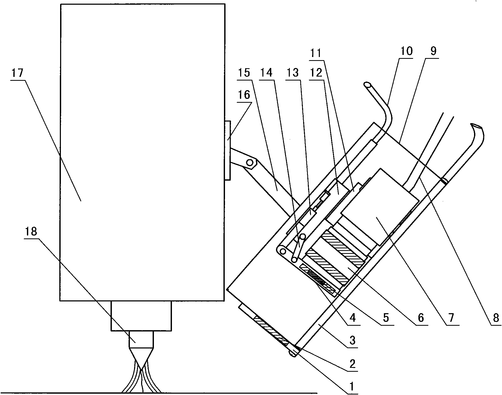
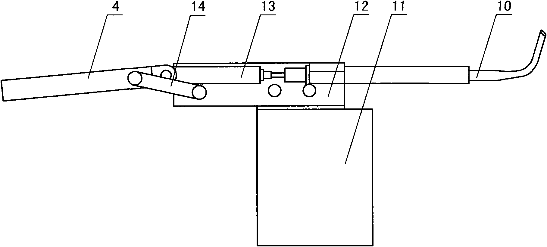
[0019] See attached Figure 1-4 , The device and method disclosed in the present invention are suitable for visual sensing monitoring in welding or cutting processes such as argon tungsten arc welding, gas metal arc welding, laser welding, and plasma arc welding.

[0020] This multifunctional arc welding visual monitoring device comprises a housing 9 of the monitoring device, a camera 7, a lens 6 and an optical filter 5 are housed in the housing 9, the lens 6 is installed at the end of the camera 7, and the video line 8 of the camera 7 It extends out of the housing 9 and is connected to an external monitor. It also includes a pneumatic linkage device installed in the housing 9. The camera adopts a CCD camera or other cameras with a lens that can adjust the aperture, wherein:

[0021] A cooling pipe 3 communicating with the outside is installed on the inner side wall of...


PUM

PropertyMeasurementUnit
Diameteraaaaaaaaaa
Wavelengthaaaaaaaaaa
Bandwidthaaaaaaaaaa

Abstract

The invention discloses a multifunctional arc welding vision monitoring device which comprises a shell, a camera, a lens, an optical filter and a pneumatic connecting bar device. A cooling tube is arranged in a bottom plate of the shell; heat-proof white glass is arranged in a front baffle; a gas cylinder bracket is fixedly connected with the bottom of the shell; a gas cylinder is fixedly connected with the top of the gas cylinder bracket; the end part of a push rod of the gas cylinder is hinged with a filter plate; and the filter plate is connected with the gas cylinder through a connecting bar. A monitoring method is as follows: the gas cylinder is discharged by controlling a switch of a solenoid valve connected with a gas tube before welding; the filter plate is rotated to be horizontal with a push rod; the central lines of the heat-proof white glass, the lens and the camera are collinear; during welding process, the gas cylinder is charged; and the filter plate is rotated to be vertical to the push rod; the central lines of the heat-proof white glass, the optical filter, the lens and the camera are collinear; after welding, the gas cylinder is discharged; the motions before welding are repeated; and the filter plate is rotated to a position outside the shooting scope of the camera. The multifunctional arc welding vision monitoring device has simple and compact structure and low cost, and has the remote monitoring function. The monitoring method is simple, and is convenient to operate.

Description

technical field [0001] The invention relates to an arc welding and cutting process quality sensing monitoring device and method, in particular to a multi-functional arc welding which integrates the functions of monitoring the arc and molten pool shape, the relative position of the electrode and the welding seam, and the surrounding environment. Visual monitoring device and monitoring method. Background technique [0002] We all know that monitoring the welding process is an integral part of the complete welding program, either directly with human eyes or with a camera. However, in some special welding conditions, such as high weld position, narrow space, online nuclear reactor or dangerous chemical occasions, it is often necessary to use automatic welding technology for welding. In this special environment, the operator cannot close The preparation and execution of the weld, usually using remote-controlled automatic welding equipment, which can only be controlled by the wel...

Claims


Application Information

Patent Timeline
IPC IPC(8): B23K9/095
Inventor 徐世龙李宝良米小刚孙潇刘飙
Owner TANGSHAN KAIYUAN WELDING AUTOMATION TECH INST
Learn More