
Iron removal device in vertical roller mill

A vertical roller mill and mill technology, applied in the direction of grain processing, etc., can solve the problems of shortening mill maintenance cycle, reducing mill utilization rate, shortening the service life of roller sleeves, etc., so as to improve mill operation and ensure Stable operation and reduced maintenance costs

Active Publication Date: 2011-08-17
TIANJIN CEMENT IND DESIGN & RES INST +2
View PDF5 Cites 7 Cited by
  • Summary
  • Abstract
  • Description
  • Claims
  • Application Information

AI Technical Summary

Problems solved by technology

However, at least 2% to 5% or more of free iron and a large amount of iron in a compound state will remain in the final steel slag that can be used for grinding. On the one hand, this part of the material is of high value and should be recycled On the other hand, due to its high density and high hardness, it is difficult to grind. After long-term operation, accumulation will occur inside the mill and on the surface of the disc liner, which will affect the stable production of the mill and cause serious abrasion to the grinding roller. Shorten the service life of the roller sleeve, shorten the maintenance cycle of the mill, increase the maintenance cost of the mill, and reduce the utilization rate of the mill

Method used


Image

  • Iron removal device in vertical roller mill
  • Iron removal device in vertical roller mill
  • Iron removal device in vertical roller mill

Examples


Embodiment Construction

[0022] In order to further understand the invention content, characteristics and effects of the present invention, the following examples are given, and detailed descriptions are as follows in conjunction with the accompanying drawings:

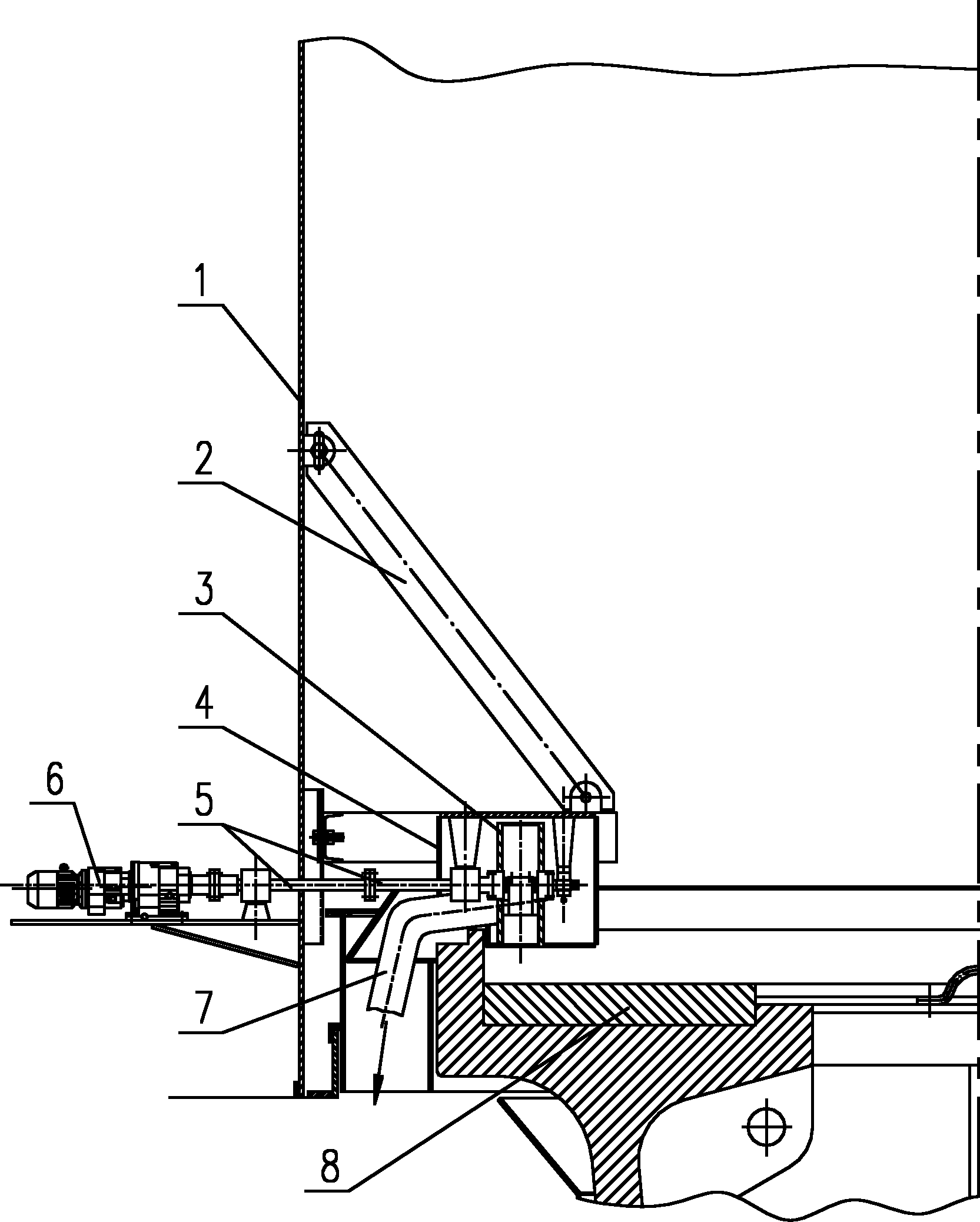
[0023] See Figure 1 ~ Figure 4 , an internal iron removal device for a vertical roller mill, comprising a truss 2 affixed to the inner wall of a shell 1 in the mill, a box 4 suspended and fixed on the truss 2, and a suspension affixed to it in the box 4 The support part Ⅰ13 and the suspension support part Ⅱ11 are suspended and fixed with the support shaft 12, and the support shaft 12 supports the drum 3, the drum 3 is fixedly connected with the power output shaft 5 of the driving mechanism, and the power output shaft 5 is suspended and supported by the suspension support part Ⅱ11; The bottom of the body 4 is provided with a feeding port, and the feeding port of the box body is located on the grinding disc 8 of the mill, and between the two a...


PUM


Abstract

The invention discloses an iron removal device in a vertical roller mill. The device comprises a truss fixedly connected on the inner wall of a shell in the mill, a box body is hung and fixed on the truss, a supporting shaft is hung and fixed in the box body, a rotary drum is supported on the supporting shaft, and the rotary drum is fixedly connected with the power output shaft of a driving mechanism; the bottom of the box body is provided with a feeding hole, the feeding hole of the box body is positioned on a millstone of the mill and positioned between two adjacent mill rollers of the mill, and the external circle surface of the rotary drum protrudes out of the feeding hole of the box body; and a permanent magnet is hung and fixed below the supporting shaft, the permanent magnet is positioned above the feeding hole of the box body, the highest point of the permanent magnet is positioned below the horizontal diameter of the rotary drum, a distance is formed between the permanent magnet and the rotary drum, an oblique discharge pipe is fixedly connected on the feeding side of the box body, and the feeding hole of the discharge pipe is positioned below the horizontal diameter of the rotary drum and adjacent to the rotary drum. The device can timely discharge milled iron granules and ferromagnetic granules on the millstone out of a millstone area on line in the milling process.

Description

technical field [0001] The invention relates to a device for removing iron, in particular to a device for removing iron in a vertical roller mill. Background technique [0002] The vertical mill is a large-scale grinding equipment, which adopts the principle of material bed grinding, integrates crushing, drying, grinding, and grading transportation, and has high production efficiency. Grind to the fineness required by the process technology. [0003] In recent years, with the great progress of material science and other related disciplines and the accumulation of practical experience, the vertical roller mill system has gradually shown its technological advantages in the field of material grinding. Compared with the traditional ball mill, it greatly reduces the unit energy consumption and achieves the effect of energy saving and emission reduction; and the vertical roller mill system has the characteristics of simple process design, less process auxiliary equipment, and low...

Claims


Application Information

Patent Timeline
Patent Type & Authority Applications(China)
IPC IPC(8): B02C23/08B02C15/00
Inventor 王奇刘子河刘箴胡斌董金利蔡晓亮尚桂来王振中郑倩魏娜
Owner TIANJIN CEMENT IND DESIGN & RES INST
Learn More