Tool for minimally invasive surgery and method for using the same

一种微创外科、工具的技术,应用在用于微创外科手术的工具领域,能够解决复杂、操作不方便等问题,达到容易移动、小体积和重量、精巧和容易外科手术操作的效果

Inactive Publication Date: 2014-11-26
郑昶旭
View PDF8 Cites 0 Cited by
  • Summary
  • Abstract
  • Description
  • Claims
  • Application Information

AI Technical Summary

Problems solved by technology

[0006] While this type of minimally invasive surgery has many advantages, it has the following disadvantages: conventional minimally invasive surgical tools are difficult to access to the surgical site, and because the end effector is attached to the rigid long shaft, the manipulation of these tools is not convenient or complicated

Method used


Image

  • Tool for minimally invasive surgery and method for using the same
  • Tool for minimally invasive surgery and method for using the same
  • Tool for minimally invasive surgery and method for using the same

Examples


Embodiment 1

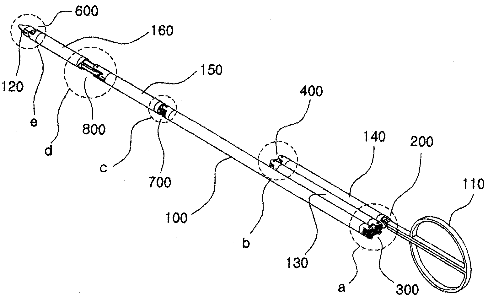
[0077] figure 1is a perspective view showing the appearance of the tool 1 for minimally invasive surgery according to the first embodiment of the present invention.

[0078] refer to figure 1 , the tool 1 for minimally invasive surgery of the present embodiment includes a shaft 100 (ie, a main shaft), an adjustment handle 110, an end effector 120, a first control shaft 130 and a second control shaft 140, a first actuation shaft 150 And second actuation shaft 160 , pitch control part 200 , first yaw control part 300 and second yaw control part 400 , pitch actuation part 600 , and first yaw actuation part 700 and second yaw actuation part 800 .

[0079] First, if figure 1 As shown, there is a main shaft 100 and a first control shaft 130 and a second control shaft 140 are positioned sequentially from one end of the main shaft 100 , and a first actuation shaft 150 and a second actuation shaft 160 are sequentially positioned from the other end of the main shaft 100 . At least a ...

Embodiment 2

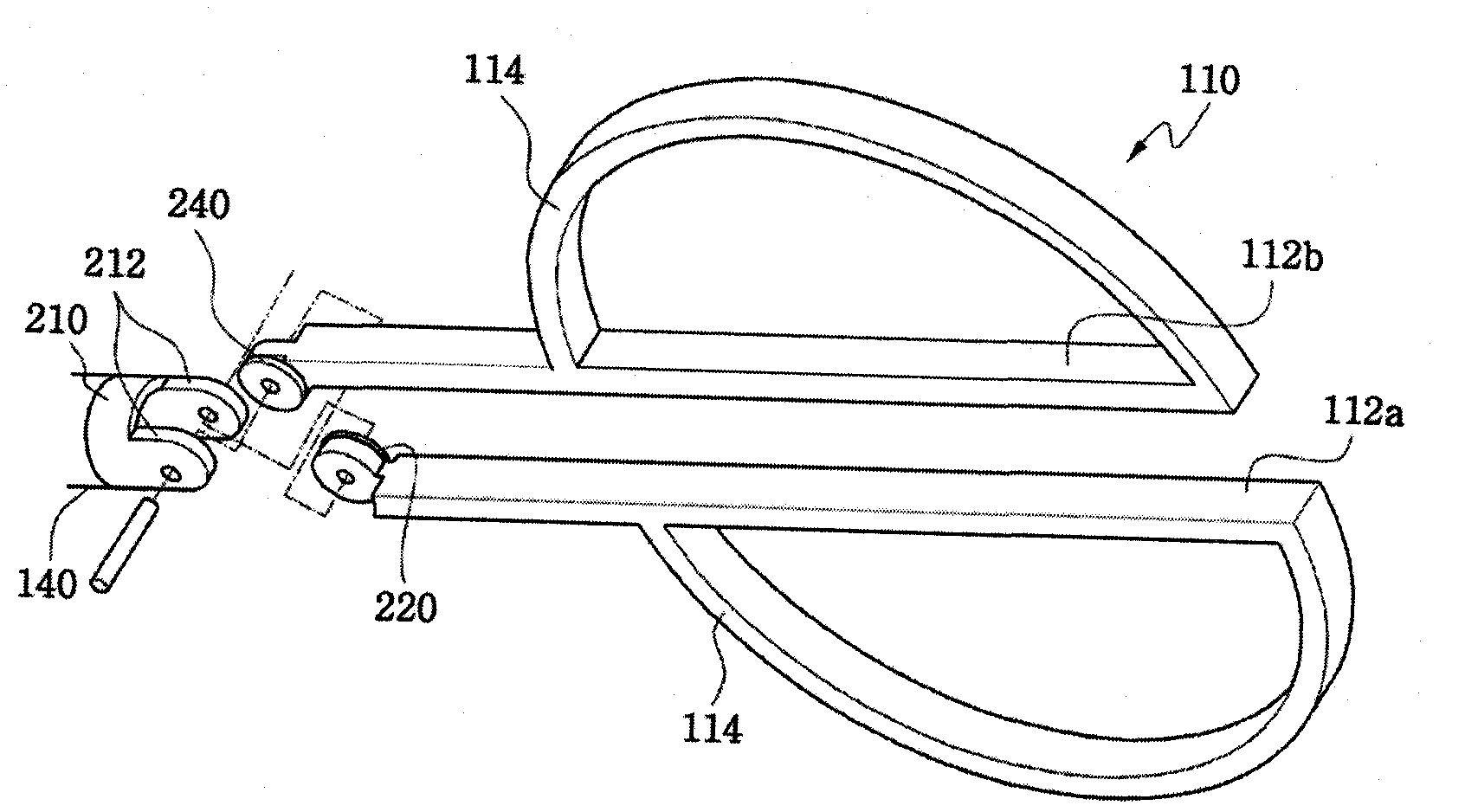
[0121] Figure 24 is a perspective view showing the connection between the adjustment handle 110 and the second control shaft 140 of the tool for minimally invasive surgery according to the second embodiment of the present invention. According to the second embodiment of the present invention, the adjustment handle 110 is connected to the second control shaft 140 through the pitch control part 200a.

[0122] More details on such structures are given below.

[0123] The pitch control part 200a may include a first pitch cable pulley 220a, a second pitch cable pulley 240a, and a third pitch cable pulley 260a. As shown in the drawing, among the first lever 112a and the second lever 112b constituting the adjustment handle 110, the first lever 112a has a first pitch cable pulley 220a fixed to its extended end and a first pitch cable pulley 220a positioned on the same rotation axis. The second pitch cable pulley 240 a to independently rotate inside the connection end 212 formed on ...

Embodiment 3

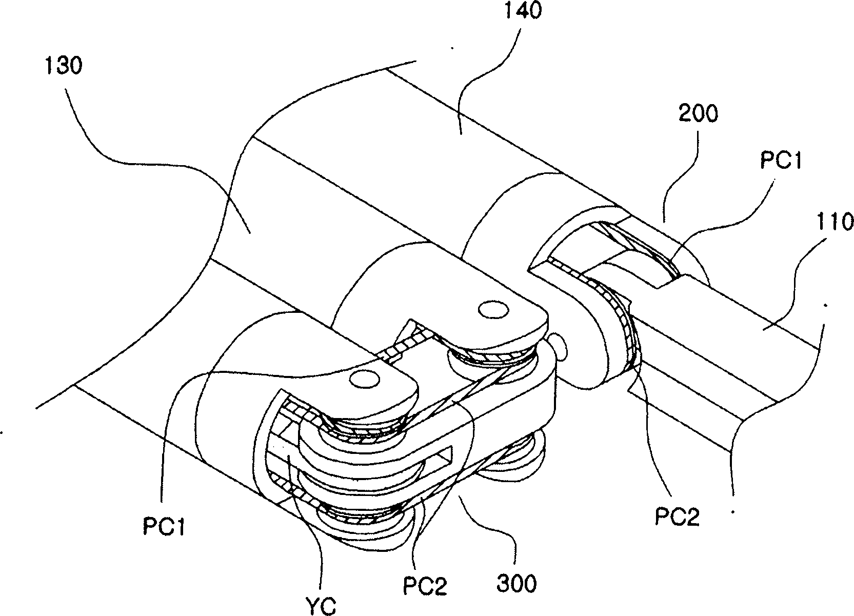
[0129] Figure 26 is a perspective view showing the appearance of a tool for minimally invasive surgery according to a third embodiment of the present invention, Figure 27 yes Figure 26 A detailed view of section 'b' in the , and Figure 28 yes Figure 26 A detailed view of section 'a' in .

[0130] According to the third embodiment of the present invention, the adjustment handle 110a for controlling the operation of the end effector 120a in the form of a hook electrode is connected to the second control shaft 140 through the pitch control part 200, and the end effector 120a is connected to the second control shaft 140 through the pitch actuation part. 600 is connected to the second actuation shaft 160 .

[0131] In this embodiment, the first pitch cable PC1 and the second pitch cable PC2 operate together to transmit the motion of the adjustment handle 110a in the pitch / yaw direction to the end effector 120a.

[0132] In addition, unlike in the first embodiment, the end...


PUM


Abstract

The present invention relates to an easy-to-control tool for minimally invasive surgery and a method for using the same. In accordance with an aspect of the present invention, there is provided a tool for minimally invasive surgery and a method for using the same comprising, a main shaft, a first control shaft and a second control shaft positioned in sequence from one end of the main shaft, a first actuating shaft and a second actuating shaft positioned in sequence from the other end of the main shaft, an adjustment handle positioned around one end of the second control shaft, an end effector positioned around one end of the second actuating shaft, a pitch control part positioned around one position of the positions between the main shaft and the first control shaft, between the first control shaft and the second control shaft, and between the second control shaft and the adjustment handle, for transferring a motion of the adjustment handle in a pitch direction to the end effector, a first yaw control part and a second yaw control part positioned around the other positions of the positions between the main shaft and the first control shaft, between the first control shaft and the second control shaft, and between the second control shaft and the adjustment handle, respectively, for transferring a motion of the adjustment handle in a yaw direction to the end effector, a pitch actuating part positioned around one position of the positions between the main shaft and the first actuating shaft, between the first actuating shaft and the second actuating shaft, and between the second actuating shaft and the end effector, a first yaw actuating part and a second yaw actuating part positioned around the other positions of the positions between the main shaft and the first actuating shaft, between the first actuating shaft and the second actuating shaft, and between the second actuating shaft and the end effector, respectively, a first pitch cable and a second pitch cable for transferring motions from the pitch control part, the first yaw control part, and the second yaw control part to the pitch actuating part, the first yaw actuating part, and the second yaw actuating part, respectively, and a yaw cable for transferring a motion from the first yaw control part to the first yaw actuating part with the first pitch cable and the second pitch cable.

Description

technical field [0001] The present invention relates to an easily controllable tool for minimally invasive surgery and a method of using it, more particularly, to a tool for minimally invasive surgery and a method of using it, said tool Actuate the end effector by adjusting the control of the handle to perform minimally invasive surgery in a dexterous and convenient manner. Background technique [0002] Minimally invasive surgery is a surgical procedure designed to cause minimal tissue trauma using instruments inserted through tiny cut openings. [0003] This minimally invasive surgical procedure relatively reduces the metabolic changes of the patient during post-operative care, thus benefiting the patient's rapid recovery. Thus, the use of this minimally invasive surgical procedure shortens the length of the patient's postoperative hospital stay and allows the patient to return to normal physical activity more quickly. Additionally, minimally invasive surgery causes less ...

Claims


Application Information

Patent Timeline
Patent Type & Authority Patents(China)
IPC IPC(8): A61B17/28
CPCA61B2017/2905A61B2017/00398A61B2017/2901A61B2019/2242A61B2017/2908A61B19/22A61B2017/2927A61B17/29A61B2017/291A61B34/70A61B34/71A61B34/30A61B17/28A61B17/00A61B17/34A61B17/32
Inventor 郑昶旭
Owner 郑昶旭
Why Eureka
Try Eureka