
Intelligent digital relay protection device

A relay protection device and intelligent technology, applied in emergency protection circuit devices, circuit devices, battery circuit devices, etc., can solve problems affecting equipment safety, increased workload of electric workers, poor safety of relay protection devices, etc. The effect of good safety isolation performance, wide application range and simple structure

Inactive Publication Date: 2011-08-03
SUNRISE GRP CO LTD
View PDF4 Cites 11 Cited by
  • Summary
  • Abstract
  • Description
  • Claims
  • Application Information

AI Technical Summary

Problems solved by technology

The relay protection device with the above structure has the following defects in the actual use process: 1. Since the voltage transformer needs to be equipped with a voltage transformer and a corresponding battery for energy storage, and special insulation measures are required, and once the insulation is broken Breakdown can easily affect the safety of equipment, so the safety of relay protection devices that use power transformers to take power is poor
In addition, due to the complex structure of using voltage transformers to obtain electricity, the cost of analog relay protection devices increases
2. In the occasions where there is no direct available power supply, the application of the relay protection device with the above structure is limited
3. When the relay protection device in the prior art is triggered, because it does not have enough prompt information, it will cause the electric staff to be unable to accurately judge the fault location, which will lead to an increase in the workload of the electric staff and an increase in the fault handling time

Method used


Image

  • Intelligent digital relay protection device
  • Intelligent digital relay protection device
  • Intelligent digital relay protection device

Examples


Embodiment Construction

[0023] The present invention will be further described below in conjunction with the accompanying drawings and specific embodiments.

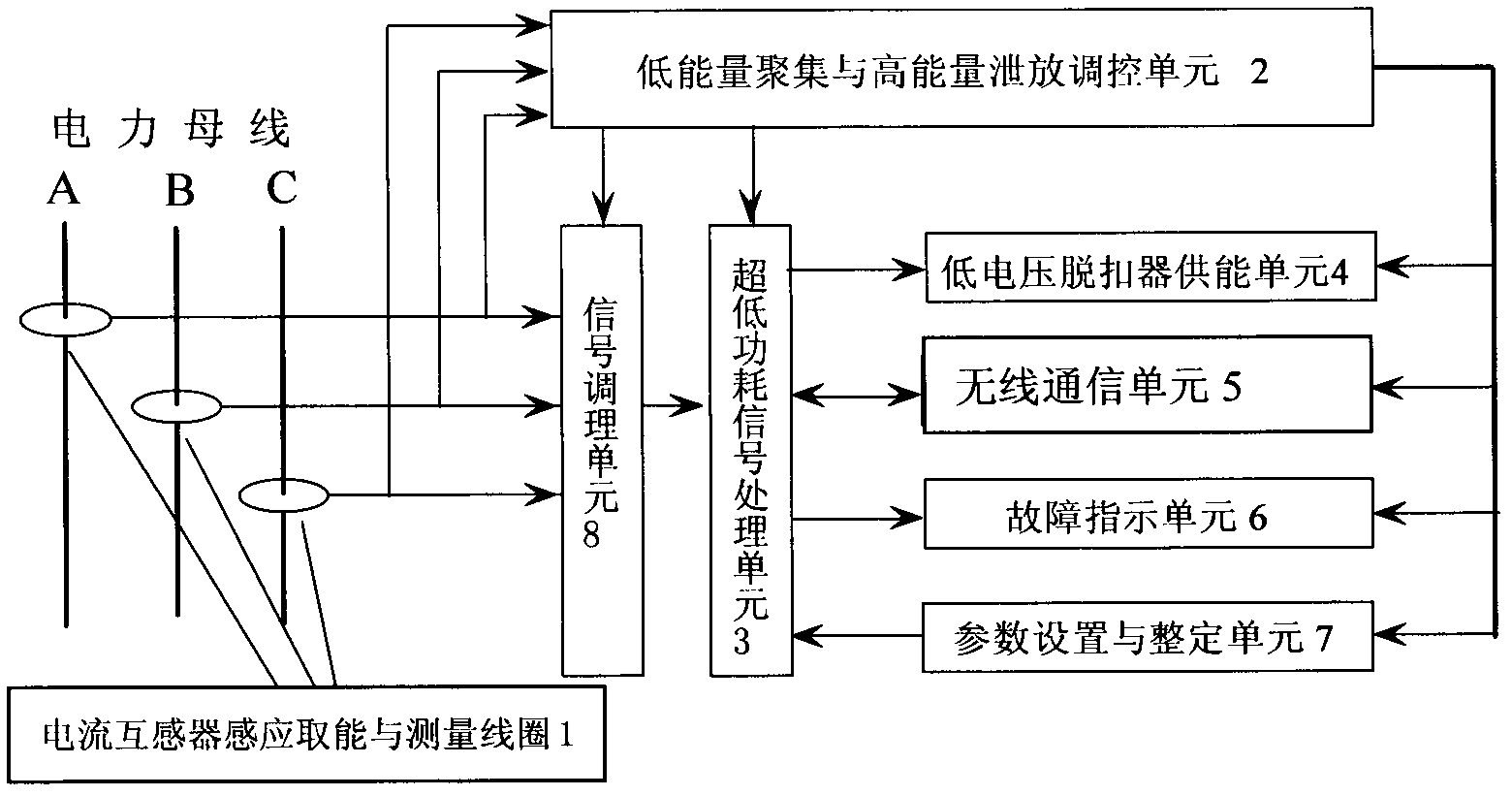
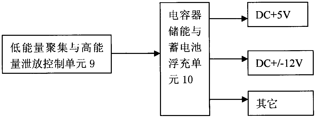
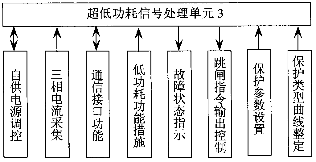
[0024] like figure 1 , figure 2 , image 3 , Figure 4 , Figure 5 As shown, an intelligent digital relay protection device of the present invention includes a current transformer induction energy acquisition and measurement coil 1 connected to a power bus, a low energy accumulation and high energy discharge control unit 2, and an ultra-low power consumption signal processing unit 3. The low-voltage release energy supply unit 4 connected to the low-voltage release, the wireless communication unit 5, the fault indication unit 6, the parameter setting and setting unit 7, and the signal conditioning unit 8, in which the current transformer senses energy and The measuring coil 1 adopts a through-heart arrangement, and its output is respectively connected to the low-energy accumulation and high-energy discharge control unit 2 of the intelligent...


PUM


Abstract

The invention discloses an intelligent digital relay protection device. A current transformer sensing energy-acquisition and measuring coil is connected with an input end of a signal conditioning unit and an input end of a low-energy gathering and high-energy discharging control unit; the output end of the low-energy gathering and high-energy discharging control unit is respectively connected with the signal conditioning unit, an ultra-low power-consumption signal processing unit, a low-voltage release energy supply unit, a wireless communication unit, a fault indication unit and a parameter setting and adjusting unit; an output end of the signal conditioning unit is connected with an input end of the ultra-low power-consumption signal processing unit; and an input / output port of the ultra-low power-consumption signal processing unit is also respectively connected with the low-voltage release energy supply unit, the wireless communication unit, the fault indication unit and the parameter setting and adjusting unit. The intelligent relay protection device has the advantages of good safety and low cost and is capable of sending a fault prompt message.

Description

technical field [0001] The invention relates to a relay protection device for a distribution network power system of 35V and below (mainly applied to 10V), in particular to an intelligent digital relay protection device installed on a pole-mounted switch or a ring network cabinet. Background technique [0002] With the planning and application development of smart grid technology, the demand for smart equipment and related technologies in smart distribution network is increasing. The development of relay protection technology has experienced electromagnetic protection, transistor protection, integrated circuit protection and microcomputer protection technology. The research of relay protection device is an important topic in the research and application of relay protection technology. At present, most relay protection devices obtain energy from the secondary side of the voltage transformer or an independent power supply (such as a DC screen) as a working power supply. For su...

Claims


Application Information

Patent Timeline
Patent Type & Authority Applications(China)
IPC IPC(8): H02H7/28H02H9/02H02J17/00H02J7/02H02J13/00H02J50/00H02J50/70
CPCY04S10/20Y02E60/725Y02E60/00
Inventor 范兴明石维坚樊建荣潘永成
Owner SUNRISE GRP CO LTD
Learn More