
Spiral phase plate with adjustable parameters

A spiral phase plate and parameter technology, applied in nonlinear optics, instruments, optics, etc., can solve the problems of high diffraction efficiency, non-adjustable topological charge, and high processing accuracy requirements, and achieve simple optical path structure, simplified manufacturing process, and conversion efficiency. high effect

Inactive Publication Date: 2011-08-03
NORTHWESTERN POLYTECHNICAL UNIV
View PDF5 Cites 14 Cited by
  • Summary
  • Abstract
  • Description
  • Claims
  • Application Information

AI Technical Summary

Problems solved by technology

However, a major problem with using computational holography is the presence of multiple orders of diffraction
Although optical vortices with different topological charges can be generated simultaneously, the diffraction efficiency of each order of vortex diffracted light is not high enough
In recent years, people have done in-depth research on the generation method of this vortex theoretically and experimentally, but the highest diffraction efficiency obtained is only 27.5%.
[0004] In addition, there are other generation methods, such as hollow waveguide method, rotating mirror optical parametric oscillation method, etc., but these methods are not as good as the above-mentioned methods in terms of scope of application and application range.
In short, the existing spiral phase mask has high processing precision requirements, and the spiral phase mask has a one-to-one correspondence with the optical wavelength, and its topological charge cannot be adjusted.

Method used


Image

  • Spiral phase plate with adjustable parameters
  • Spiral phase plate with adjustable parameters
  • Spiral phase plate with adjustable parameters

Examples


Embodiment 1

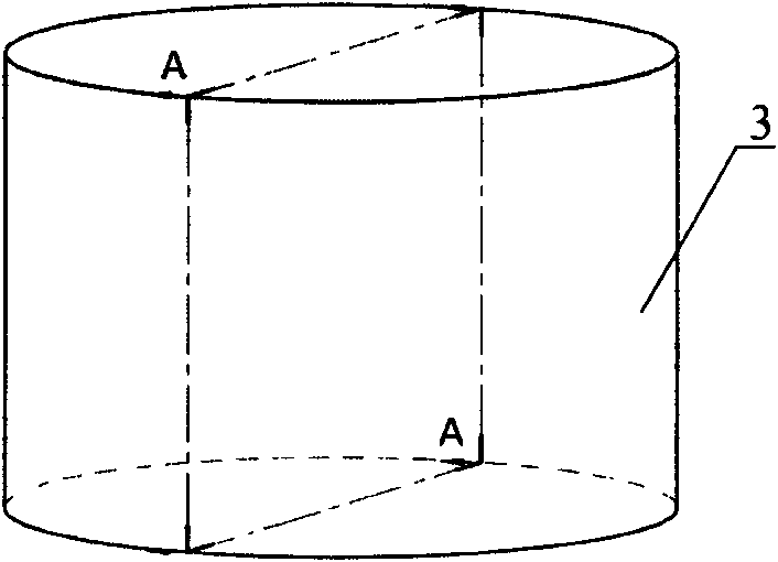
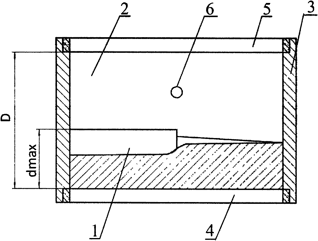
[0043] refer to Figure 1-a to Figure 2-b . This embodiment includes a transparent solid helical phase plate 1 (left-handed from thick to thin), a refractive index matching liquid 2 , and a cylindrical transparent container 3 . The bottom plane of the solid spiral phase plate 1 is in close contact with the incident surface 4 at the bottom end of the cylindrical transparent container 3 . The cavity between the upper end surface 5 of the cylindrical transparent container 3 and the spiral phase plate 1 is filled with a refractive index matching liquid 2 . A matching liquid injection hole 6 is opened on one side of the cylindrical container. In this embodiment, matching liquids with different refractive indices need to be selected in advance and injected through the injection hole 6 . The solid helical phase plate is made of transparent materials. In this embodiment, crown glass is taken as an example to make a solid helical phase plate with a thickness difference Δd=0.02 mm. U...

Embodiment 2

[0050] refer to Figure 3-a to Figure 4-b . This embodiment includes a transparent solid helical phase plate 1 (left-handed from thick to thin), a refractive index matching liquid 2 and a cylindrical transparent container 3 . The outer surfaces of the incident end face 4 and the upper end face 5 of the cylindrical container are covered with transparent electrodes 7 and 8, respectively. The bottom plane of the solid spiral phase plate 1 is in close contact with the bottom incident surface 4 of the cylindrical transparent container 3 . The cavity between the upper end surface 5 of the cylindrical transparent container 3 and the spiral phase plate 1 is filled with a refractive index matching liquid 2 . The transparent solid helical phase plate 1 is made of electro-optic crystal, and one of its electric field-induced dielectric main axes (denoted as z′ axis) is perpendicular to the bottom surface of the phase plate and points to the top, parallel to the incident light beam, and ...

Embodiment 3

[0064] refer to Figures 5-a to 6-b . This embodiment includes a transparent solid helical phase plate 1 (cuboid, the bottom surface is a square with a side length 1, and the helical part is left-handed from thick to thin, as shown in FIG. 6 ), a refractive index matching liquid 2, and a cuboid container 3 . The bottom plane of the solid spiral phase plate 1 is in close contact with the incident surface 4 at the bottom end of the square container 3 . The cavity between the upper end surface 5 of the square container 3 and the spiral phase plate 1 is filled with a refractive index matching liquid 2 . The outer surfaces of the two opposite sides of the cuboid container 3 are respectively covered with the first opaque electrode 9 and the second opaque electrode 10 . The transparent solid helical phase plate 1 is made of electro-optic crystal, one of its electric field induced dielectric main axes (denoted as z′ axis) is parallel to the bottom surface of the phase plate, perpend...


PUM

PropertyMeasurementUnit
refractive indexaaaaaaaaaa

Abstract

The invention relates to a spiral phase plate with adjustable parameters, characterized in that a solid spiral phase plate is fixed on the end surface at one side of a transparent container while the spiral surface faces inwards; the container is filled with refraction rate matching liquid to form a liquid spiral phase plate complementary to the solid spiral phase plate; and the refraction rate difference between the solid spiral phase plate and the matching liquid and the topological charge value m of an optical vortex meets a relational expression in the specification. On the premise that the advantages of high conversion rate, simple light path structure, and the like of a traditional spiral phase plate are guaranteed, the spiral phase plate with the adjustable parameters, which is provided by the invention, is beneficial to simplification of the manufacture process, realization of adjustable parameters and flexible control of the topological charge value for generating the opticalvortex. In addition, the spiral phase plate provided by the invention has no requirement for the wavelength of a light source and has favorable suitability.

Description

technical field [0001] The invention relates to a helical phase plate with adjustable parameters, which is used to modulate any wavelength monochromatic light source to generate an optical vortex with any topological charge, and is regarded as a helical phase plate with adjustable parameters. Background technique [0002] Due to its unique phase structure and topological properties, optical vortex has attracted extensive attention in the fields of basic research and applied research in recent decades. In the field of optics, if there is a phase singularity in the center of the optical wave field, and the phase continuously changes spirally around the singularity, the optical wavefront will rotate in a spiral manner in the direction of propagation, forming a spiral wavefront, which is very similar to fluid The vortex phenomenon in, so this kind of light wave is called "optical vortices" (OpticalVortices). The central intensity of this type of beam is strictly zero due to des...

Claims


Application Information

Patent Timeline
Patent Type & Authority Applications(China)
IPC IPC(8): G02F1/03
Inventor 杨德兴赵腾
Owner NORTHWESTERN POLYTECHNICAL UNIV
Learn More