
Microwave staring imaging correlation method

A microwave staring and imaging technology, used in radar technology, aerospace remote sensing and precision guidance, can solve problems such as low resolution and achieve the effect of high resolution imaging

Inactive Publication Date: 2011-08-03
UNIV OF SCI & TECH OF CHINA
View PDF2 Cites 19 Cited by
  • Summary
  • Abstract
  • Description
  • Claims
  • Application Information

AI Technical Summary

Problems solved by technology

[0005] Therefore, the existing conventional real-aperture microwave staring imaging technology only processes the received signal, resulting in low-resolution imaging

Method used


Image

  • Microwave staring imaging correlation method
  • Microwave staring imaging correlation method
  • Microwave staring imaging correlation method

Examples


Embodiment Construction

[0025] Embodiments of the present invention are described in detail below, examples of which are shown in the drawings, wherein the same or similar reference numerals designate the same or similar elements or elements having the same or similar functions throughout. The embodiments described below by referring to the figures are exemplary only for explaining the present invention and should not be construed as limiting the present invention.

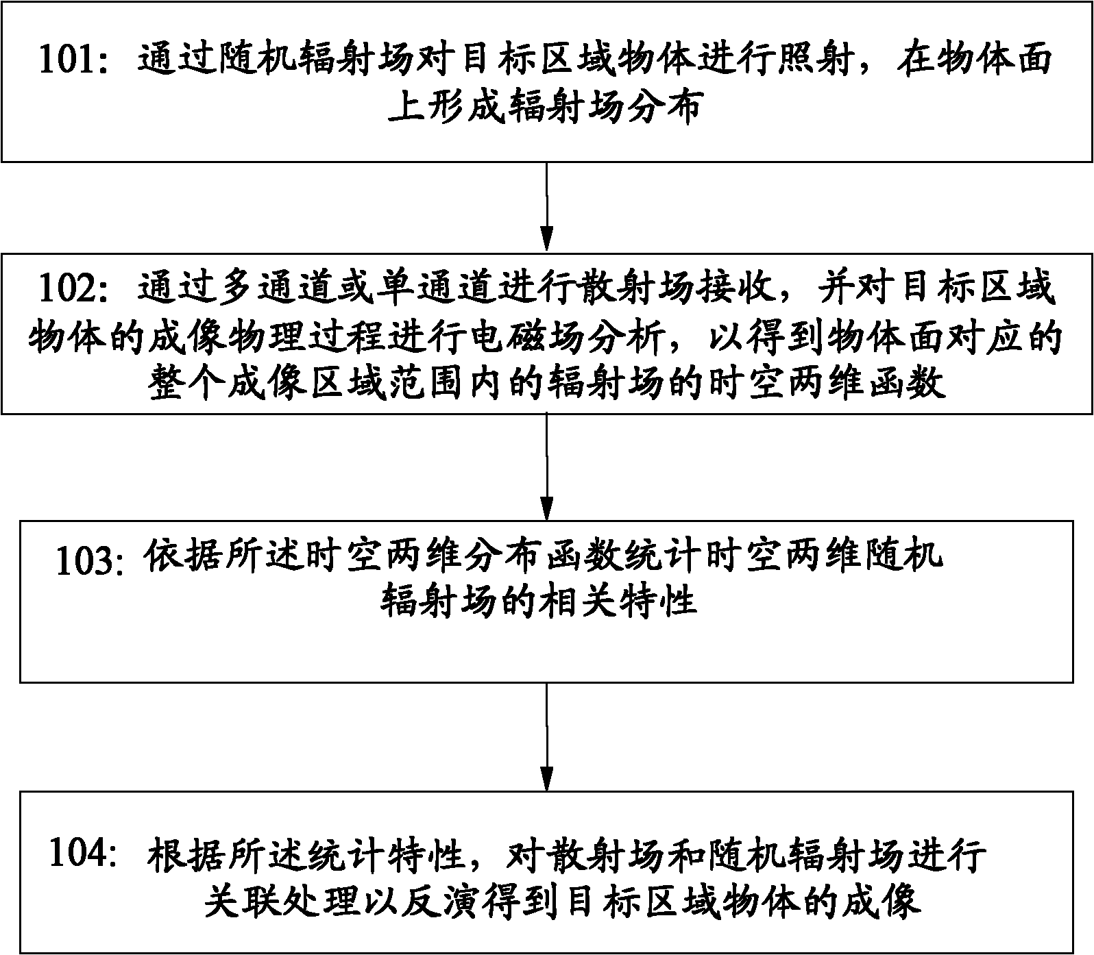
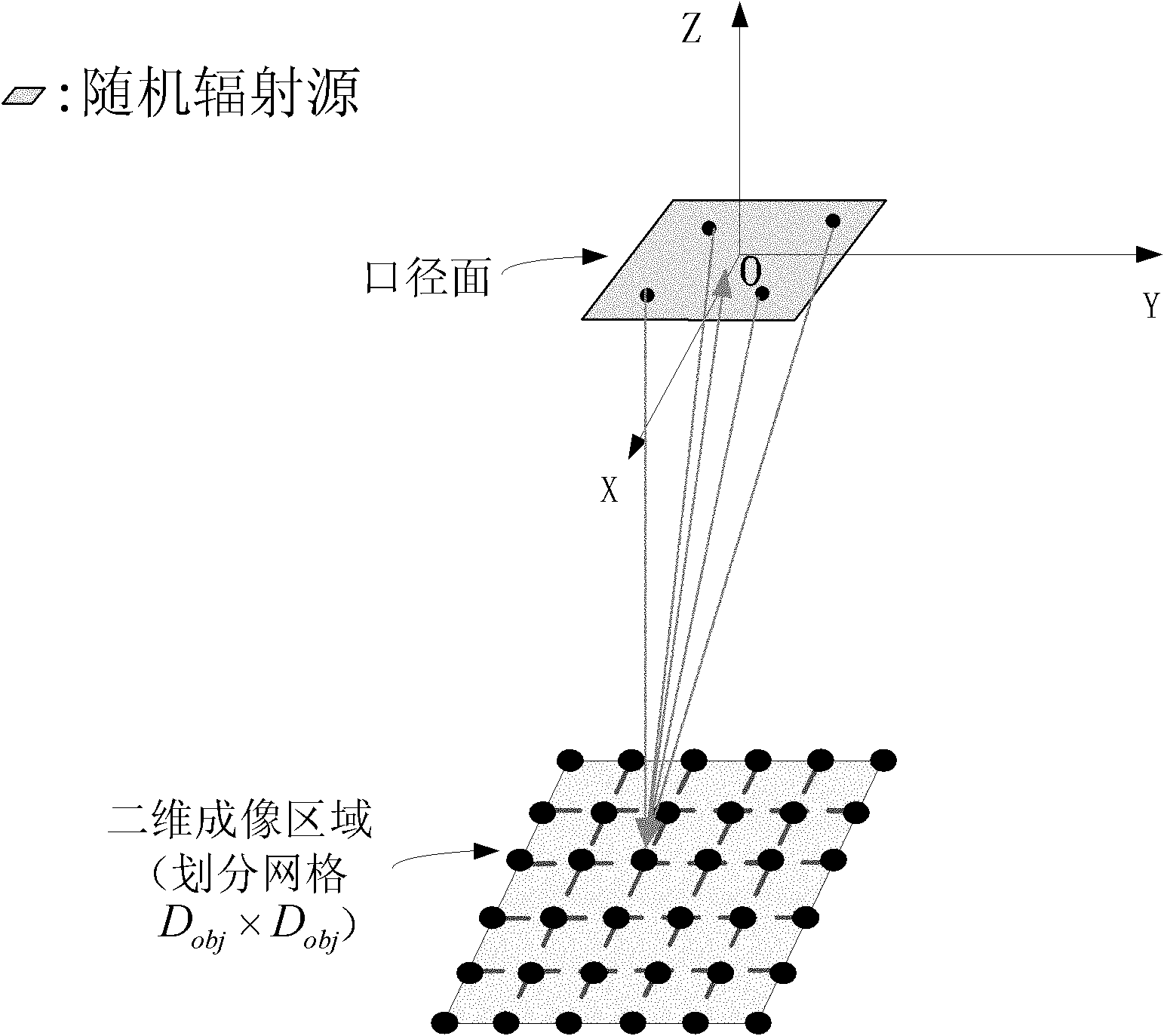
[0026] now refer to figure 1 , figure 1 It is a flowchart of a microwave staring imaging correlation method according to an embodiment of the present invention. This figure shows the correlation processing technology in the high-resolution microwave staring imaging based on the space-time two-dimensional random radiation field of the present invention. The processing details in each specific step in the present invention are given in detail below in combination with the basic principle of electromagnetic field. The specific description...


PUM


Abstract

The invention discloses a microwave staring imaging correlation method which comprises the following stepsof irradiating a target area object through a random radiation field and forming the distribution of the radiation field on an object surface; receiving a scattering field through a multi-channel or a single channel and carrying out electromagnetic field analysis to the imaging physical process of the target area object to obtain a time and space two-dimensional radiation field function corresponding to the object surface within the whole imaging area scope; counting the relevant characteristics of a time and space two-dimensional radiation field according to the time and space two-dimensional radiation field function; and carrying out correlated processing on the scattering field and the random radiation field according to the statistic characteristics to obtain the imaging of the target area object through inversion. The microwave staring imaging correlation method can be combined with the scattering field and the time and space two-dimensional radiation field to realize the high-resolution target imaging.

Description

technical field [0001] The invention belongs to the fields of radar technology, spaceflight remote sensing and precise guidance. Specifically, the invention relates to a correlation processing technology in microwave staring imaging. Background technique [0002] Traditional microwave staring radar imaging mainly uses real aperture technology. Real-aperture imaging radar is typically represented by beam-scanning radar. Its imaging processing technology relies on the correlation matching between the scattered received signal and the signal of the transmitting source. Since the signal of the transmitting source is not used in the spatial resolution of the target during this process, the The spatial resolution of the target only depends on the spatial configuration of the emitter array, that is, it is only determined by the beam width of the emitter array in the traditional sense, and the details of the illuminated target within the beam cannot be resolved. [0003] As one of ...

Claims


Application Information

Patent Timeline
Patent Type & Authority Applications(China)
IPC IPC(8): G01S13/89G01S13/90
Inventor 王东进马远鹏陆广华尹治平何学智孟青泉刘畅畅
Owner UNIV OF SCI & TECH OF CHINA
Learn More