


Quick Research
Generate reliable direction feasibility study reports for your R&D in just a few steps.

Technical Q&A
Discover and master advanced knowledge NOW. Basics, ideas, possibilities, all at once.

Find Solutions
As an expert in R&D theories, this can generate solutions to your technical problems instantly.

Evaluate Feasibility
Analyze your overall solution with one click, know your potential R&D risks in advance.

Monitor Landscape
Get weekly tech updates, stay abreast of the latest tech innovations and key insights.
Bearing device
A bearing device and ball bearing technology, applied in the field of bearing devices, can solve the problems of large outer diameter, high processing cost, high material cost, and many cutting parts, etc., and achieve the effect of reducing the outer diameter, reducing the material cost, and improving the function
- Summary
- Abstract
- Description
- Claims
- Application Information
AI Technical Summary
Problems solved by technology
Method used
Image


Examples
Embodiment Construction
[0022] (structure)
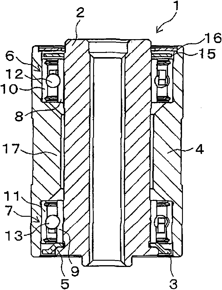
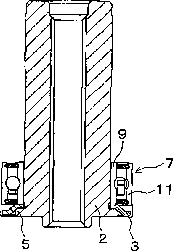
[0023] Figure 1A and Figure 1B Shown is a pivot assembly bearing device 1 as a bearing device according to an embodiment. The pivot assembly bearing device 1 is used for swingably supporting a rocker arm mounted with a magnetic head for reading and writing information in a hard disk drive. The pivot unit bearing device 1 is used by being fitted into a through hole of a not-shown rocker block (E block).
[0024] The pivot unit bearing device 1 includes a shaft 2 . The shaft 2 is rotatably held by a pair of ball bearings 6 and 7 . That is, the ball bearing 6 holds the rolling elements 12 between the inner ring 8 and the outer ring 10 , and the ball bearing 7 holds the rolling elements 13 between the inner ring 9 and the outer ring 11 . Furthermore, the inner rings 8 and 9 are fixed to the outer periphery of the shaft 2, and the outer rings 10 and 11 are fixed to the inner side of the sleeve 4 which is a cylindrical structure. Lubricants such as grease...
PUM
 Abstract
Description
Claims
Application Information
 - R&D Engineer
- R&D Manager
- IP Professional
- Industry Leading Data Capabilities
- Powerful AI technology
- Patent DNA Extraction
Browse by: Latest US Patents, China's latest patents, Technical Efficacy Thesaurus, Application Domain, Technology Topic, Popular Technical Reports.
© 2024 PatSnap. All rights reserved.Legal|Privacy policy|Modern Slavery Act Transparency Statement|Sitemap|About US| Contact US: help@patsnap.com