
Valve plate structure improving efficiency of piston compressor

A compressor and piston type technology, which is applied in the direction of liquid variable capacity machinery, mechanical equipment, variable capacity pump components, etc., can solve the problems of high cost, easy leakage, complex process, etc., and achieve the goal of reducing processing costs and improving efficiency Effect

Inactive Publication Date: 2011-08-03
上海英范特冷暖设备有限公司
View PDF5 Cites 2 Cited by
  • Summary
  • Abstract
  • Description
  • Claims
  • Application Information

AI Technical Summary

Problems solved by technology

Although the special double-layer handle valve plate can also achieve the effect of reducing the clearance, but the cost is high, the process is complicated, and it is easy to leak

Method used


Image

  • Valve plate structure improving efficiency of piston compressor
  • Valve plate structure improving efficiency of piston compressor
  • Valve plate structure improving efficiency of piston compressor

Examples


Embodiment Construction

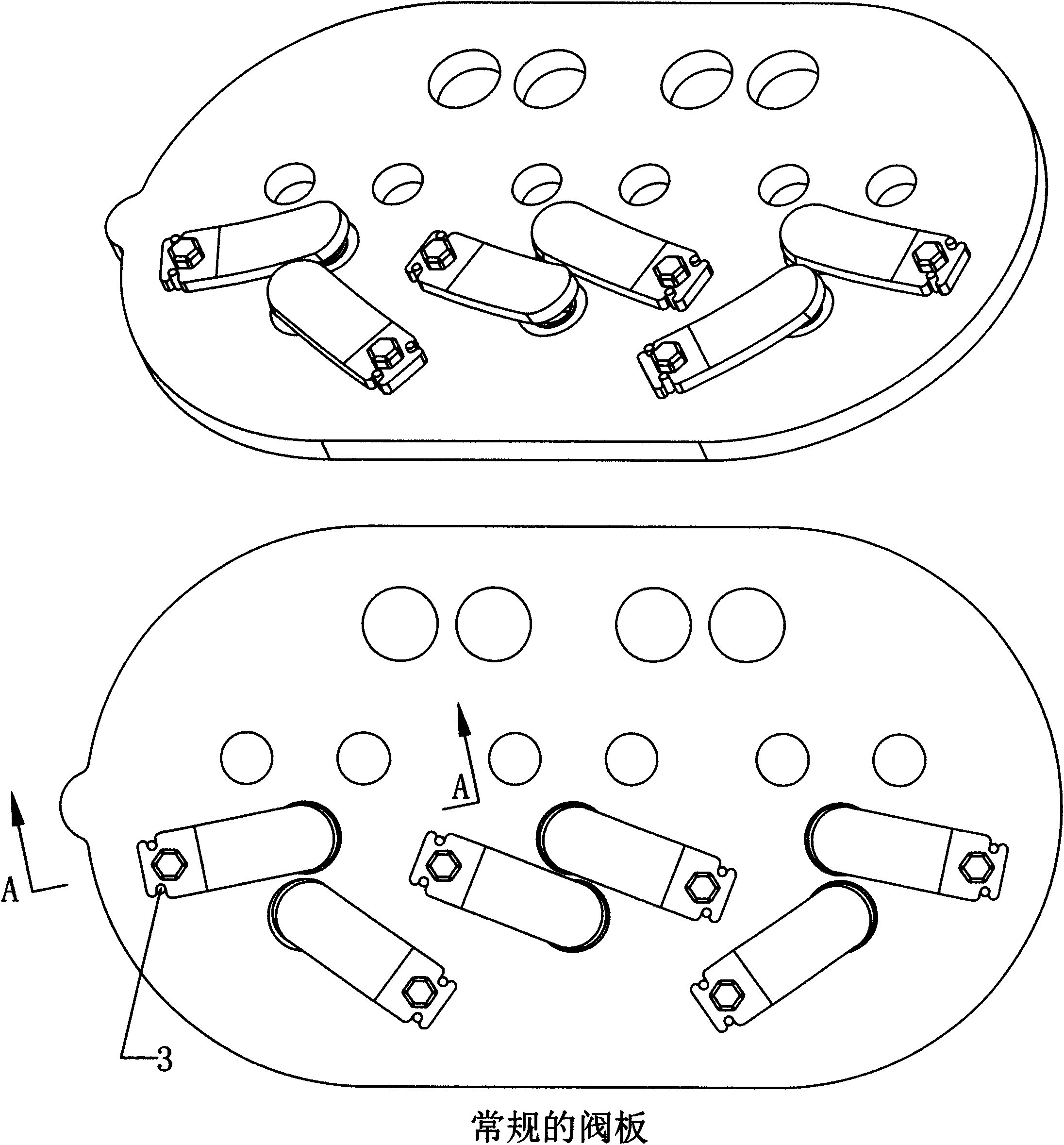
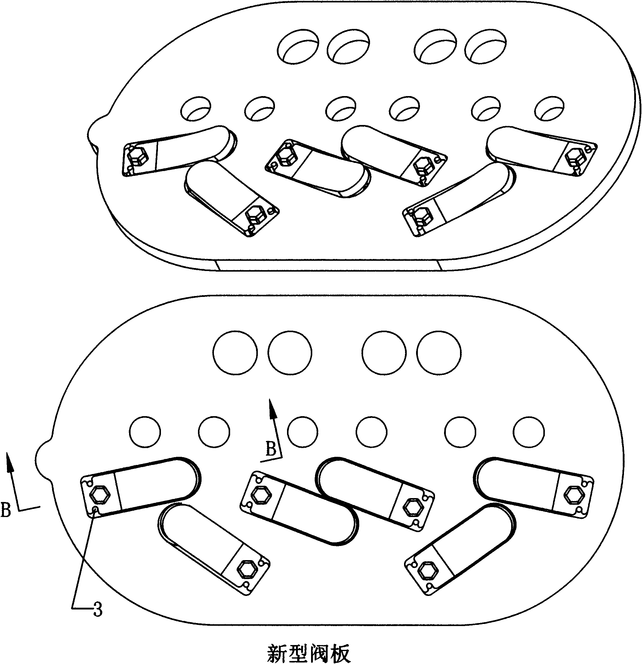
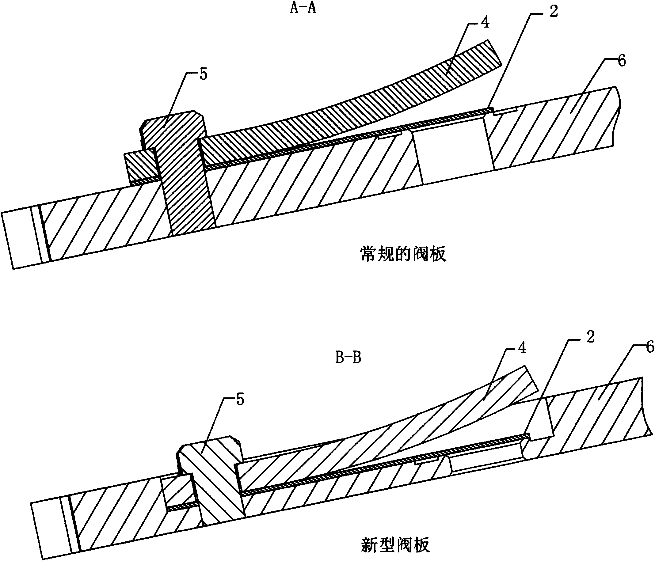
[0009] A valve plate structure for improving the efficiency of a piston compressor, which includes a valve plate assembled from an intake valve plate 1, an exhaust valve plate 2, a valve plate pin 3, a baffle plate 4, fixing bolts 5, and a valve plate body 6 Composite structure (see figure 1 and figure 2 ). The difference between the two valve plates is that the exhaust valve plate, valve plate pin, baffle plate and fixing bolts of the conventional valve plate are installed on the surface plane of the valve plate body, while the exhaust valve plate, valve plate and valve plate of the new valve plate are installed on the surface plane of the valve plate body Sheet pin, baffle plate, locating pin are installed on the processed plane of valve plate body. The main difference between these two valve plates is that the height of the vent hole of the former is 8mm, while the height of the vent hole of the latter is 2-3mm. Because the diameter of the vent hole is the same, the latt...


PUM


Abstract

The invention discloses a valve plate structure improving the efficiency of a piston compressor. The valve plate structure comprises a valve plate combination structure formed by assembling an air inlet valve sheet, an air release valve sheet, a valve sheet pin, a baffle plate, a fixing bolt, a valve plate body and the like, and is characterized in that: by a new method, for one side of the air release valve sheet of the valve plate, the requirements of the whole parallelism, flatness, and surface finish degree of the valve plate are not needed to be considered; and only in a limited area of the sealing surface of the air release valve sheet, the mounting surface of the air release valve sheet is processed by a special processing mode, the thickness of a vent hole is controlled to be 2 to 3mm, and the requirements of flatness and finish degree of an effective area can be met. By the method, the clearance of the vent hole, which is produced by the thickness of the valve plate is reduced by 62 to 75 percent, so that the efficiency of the piston compressor is improved greatly.

Description

technical field [0001] The invention belongs to the technical field of piston compressors, in particular to the structure of a valve plate. technical background [0002] Piston compressor is composed of body, crankshaft, cylinder head, valve plate, connecting rod, piston, motor, motor cover, bearing seat, bottom cover and other main components. The crankshaft is turned by the motor, and the crankshaft drives the connecting rod and the piston to move up and down in the cylinder. A valve plate is installed on the cylinder surface, and the valve plate is provided with an air intake hole and an exhaust hole, and an air intake valve sheet is arranged below the air inlet hole, and an exhaust valve sheet is installed above the air outlet hole. When the piston moves down, the exhaust valve is automatically closed due to high pressure. The pressure in the cylinder bore decreases as the piston moves down. When the pressure in the cylinder bore is lower than the intake pressure, the ...

Claims


Application Information

Patent Timeline
Patent Type & Authority Applications(China)
IPC IPC(8): F04B39/10
Inventor 袁晓华付德春
Owner 上海英范特冷暖设备有限公司
Learn More