LED (light-emitting diode) driving and dimming method for pulse-by-pulse current adjustment by adopting frequency doubled of power frequency

A technology of LED drive and double power frequency, which is applied in light sources, electric light sources, lighting devices, etc., can solve problems such as unsatisfactory lighting effects, obvious color temperature changes, and prominent lighting safety hazards, and achieve large-scale stable dimming, overcome Color temperature drift, the effect of expanding the application field

Inactive Publication Date: 2011-07-27
西安明泰半导体科技有限公司
View PDF4 Cites 7 Cited by
  • Summary
  • Abstract
  • Description
  • Claims
  • Application Information

AI Technical Summary

Problems solved by technology

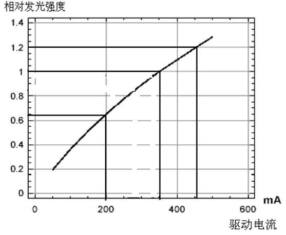
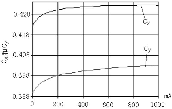
[0004] The purpose of the present invention is to provide a LED driving and dimming method that adopts double power frequency pulse-by-pulse current regulation, which solves the problems in the prior art that the color temperature changes obviously, the actual lighting effect is not ideal, and the hidden danger of lighting safety is prominent.

Method used


Image

  • LED (light-emitting diode) driving and dimming method for pulse-by-pulse current adjustment by adopting frequency doubled of power frequency
  • LED (light-emitting diode) driving and dimming method for pulse-by-pulse current adjustment by adopting frequency doubled of power frequency
  • LED (light-emitting diode) driving and dimming method for pulse-by-pulse current adjustment by adopting frequency doubled of power frequency

Examples


Embodiment 1

[0027] Technical requirements: 288 0.1W 3528 / 3410 SMT encapsulated LED lamp beads are used to make 18W T-tube fluorescent lamps, which can be dimmed.

[0028] First select the actual maximum working current of the LED, take 24mA, the maximum power of the lamp is 288×0.024×3.3=22.8W, and the actual maximum output power is 18W, then the duty cycle D=18÷22.8=80%

[0029] At the same time, 288 LED lamps are combined in 24 series x 12 parallel matrix, and the total constant current is 24mA x 12 = 288mA.

[0030] Figure 5 It is a schematic diagram of the T tube solution in this embodiment, using 288 0.1W 3528 / 3410 SMT packaged LED lamp beads, 24 strings × 12 parallel matrix combination, 288mA constant current, 80% duty cycle to achieve 18W output, 80% duty cycle Adjust down for continuous dimming.

Embodiment 2

[0032] Technical requirements: Use 84 1W-3W high-power LEDs to make a 100W street light source with half-power settings.

[0033] Choose a product with a single LED of 1.5W, and refer to the product parameter table to know that the working current of a single LED is 575mA, and the duty cycle D=100W÷(1.5×84)=0.8 when the full power is 100W, which corresponds to the duty cycle at half power is 0.4.

[0034] 84 LEDs adopt 42 strings × 2 parallel matrix, the total constant current is 2 × 575 mA = 1.15A, and the power frequency is doubled to 100Hz / 120Hz PWM switching frequency.

[0035] Image 6 It is a schematic diagram of the 100W street lamp solution in this embodiment, 84 pieces of 1W-3W high-power LEDs, using 42 series × 2 parallel matrix mode, power frequency double frequency 100Hz / 120Hz PWM modulation working mode, constant current 1.15A, full power 100W Select 80% for the duty cycle, and 40% for the half-power duty cycle.


PUM


Abstract

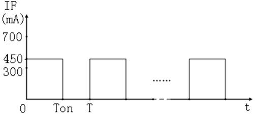
The invention discloses an LED (light-emitting diode) driving and dimming method for pulse-by-pulse current adjustment by adopting a frequency doubled of a power frequency, and the method is implemented through the following concrete steps: as for an LED matrix combination assembled based on technical requirements, determining the duty cycle D based on the working state and working current of an LED, wherein D=the optical power required to be output / state power; then, selecting the 100Hz / 120Hz modulation frequency doubled of a power frequency; and finally driving and dimming in a PWM (pulse-width modulation) mode based on the obtained duty cycle and selected modulation frequency parameters. The invention has the beneficial effects that by adopting the frequency doubled of a power frequency for PWM modulation, in each doubled power frequency period, constant current is maintained unchanged, and the pulse width is modulated pulse by pulse, thus overcoming the defect of color temperature drift caused by modulation of the LED, realizing stable dimming within a large range and expanding the application field of the LED.

Description

technical field [0001] The invention belongs to the technical field of LED semiconductor solid-state lighting, and relates to an LED driving and dimming method that adopts pulse-by-pulse current regulation at twice the power frequency. Background technique [0002] LED driver is the core of LED applications. With the expansion of LED applications, higher and newer requirements are put forward for LED drivers. LED light sources must not only be driven by a stable constant current, but also be able to work stably at half power (street lights, tunnel lights, etc.). In some occasions, it is also necessary to be able to continuously adjust the light. [0003] The existing technology realizes the dimming function by simply adjusting the driving current, which will bring about changes in the color temperature of the LED, seriously affecting the actual lighting effect and causing lighting safety hazards. LED lighting represented by the US "Energy Star" at home and abroad Standards ...

Claims


Application Information

Patent Timeline
Patent Type & Authority Applications(China)
IPC IPC(8): H05B37/02
Inventor 邢先锋刘义芳王清平
Owner 西安明泰半导体科技有限公司
Why Eureka
Try Eureka