
Pipe-in-pipe type heat exchanger and pipeline system with same

A tubular heat exchanger and heat exchanger technology, applied in the field of sanitary heat exchange systems, can solve the problems of imprecise manufacturing process, high cost, and large space occupation, and achieve convenient and quick installation, large heat transfer coefficient, and low temperature fast effect

Inactive Publication Date: 2011-07-27
E PHARMA SHANGHAI PHARMA EQUIP
View PDF6 Cites 1 Cited by
  • Summary
  • Abstract
  • Description
  • Claims
  • Application Information

AI Technical Summary

Problems solved by technology

[0003] However, in the existing tubular heat exchanger, the heat exchange between the high-temperature fluid and the low-temperature fluid is not sufficient, so it is difficult to achieve the predetermined cooling effect. In addition, the connection process between the various pipelines is complicated. Once the manufacturing process If it is not tight, it is easy to cause leakage at the welds of each pipeline, causing cross-contamination and wasting energy; and there are many pipelines arranged in a predetermined way inside the shell. During the installation process of the entire heat exchanger, the installation process is complicated and takes up space. Many and high cost

Method used


Image

  • Pipe-in-pipe type heat exchanger and pipeline system with same
  • Pipe-in-pipe type heat exchanger and pipeline system with same
  • Pipe-in-pipe type heat exchanger and pipeline system with same

Examples


Embodiment Construction

[0027] The following will clearly and completely describe the technical solutions in the embodiments of the present invention with reference to the accompanying drawings in the embodiments of the present invention. Obviously, the described embodiments are only some, not all, embodiments of the present invention. Based on the embodiments of the present invention, all other embodiments obtained by persons of ordinary skill in the art without creative efforts fall within the protection scope of the present invention.

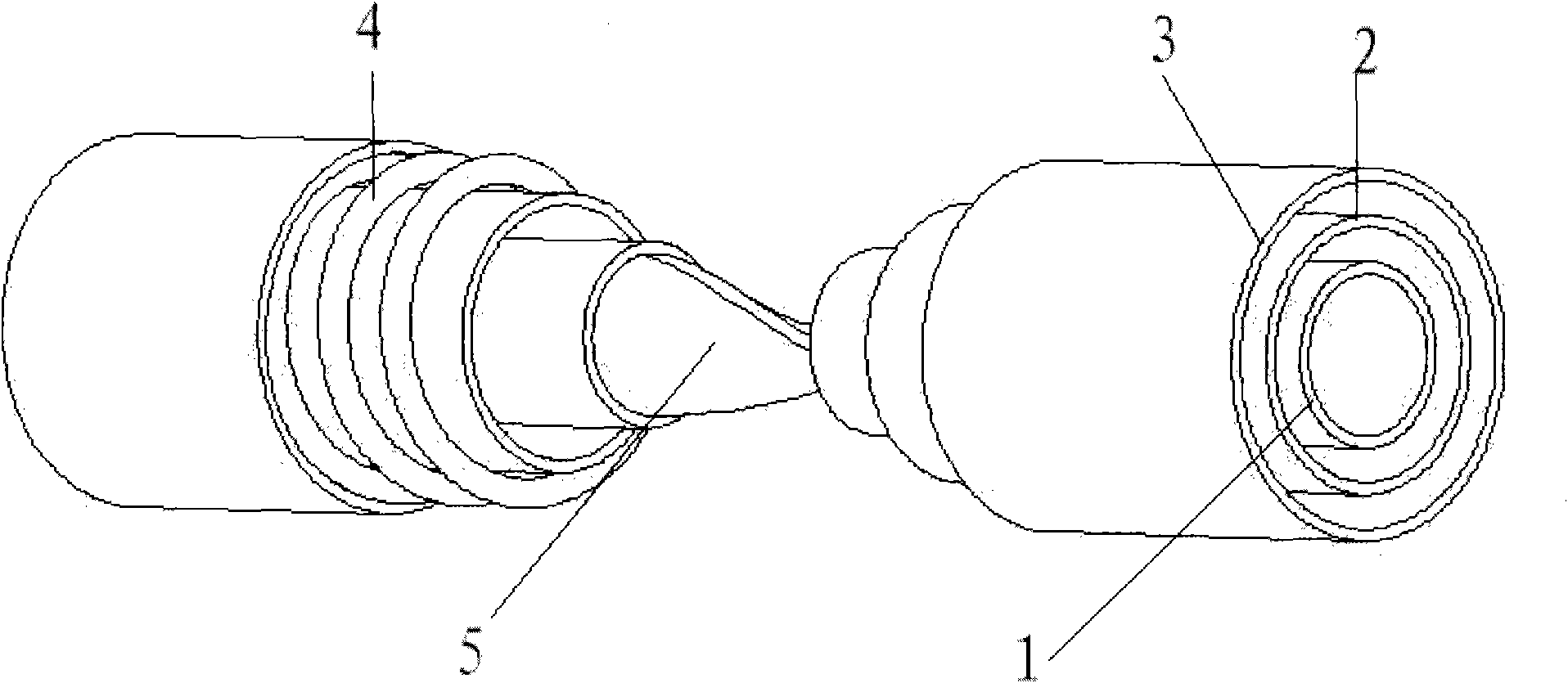
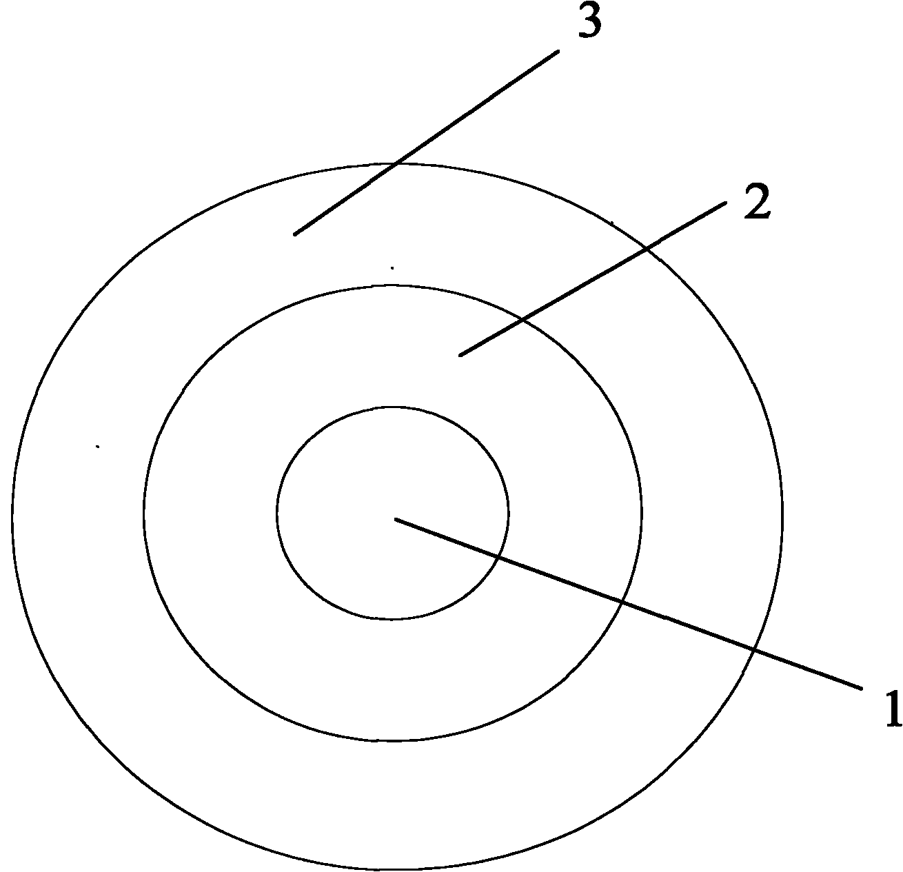
[0028] The internal structure diagram of the tube-in-tube heat exchanger disclosed in the embodiment of the present invention is as follows figure 1 As shown, the entire heat exchanger pipe is nested and manufactured by three steel pipes of different sizes. From the inside to the outside, there are inner channel 1, middle channel 2 and outer channel 3; in the outer channel 3, there is a spiral guide The tube 4 and the spiral guide tube 4 are wound on the outside of...


PUM


Abstract

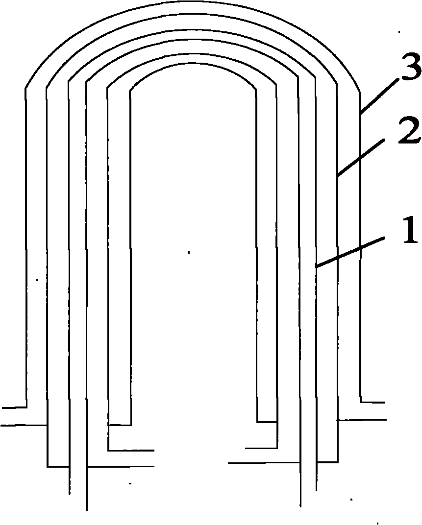
The embodiment of the invention discloses a pipe-in-pipe type heat exchanger. The heat exchanger is formed in a way that three layers of steel pipes with different dimensions are embedded with one another and are manufactured into a whole, and the three layers of steel pipes are sequentially an internal passage, a middle passage and an external passage from inside to outside; and the three layers of passages are bent by 180 degrees to form a U shape. The invention also discloses a pipeline system with the heat exchanger. The pipeline system comprises a pipe-in-pipe heat exchanger, a terminal device, a main pipeline, a first pipeline, a second pipeline, a third pipeline and a fourth pipeline. The pipe-in-pipe type heat exchanger comprises three layers of pipelines that are formed by one step; low-temperature fluid passes by the internal pipeline and the external pipeline; high-temperature fluid passes by the middle pipeline and carries out heat exchange with the low-temperature fluid in the internal pipeline and the external pipeline simultaneously so that the heat exchanging process is sufficient, the heat transfer coefficient is large, the temperature of the high-temperature fluid can be well reduced, and the temperature reduction speed is quick; furthermore, as the pipeline is formed by one step, welding is not adopted in the pipeline, and no dead corners exist in the pipeline, the leakage between the pipelines can be prevented effectively; the risk of cross contamination can be avoided, and the assembly is convenient and quick.

Description

technical field [0001] The invention relates to a sanitary heat exchange system, more specifically, to a tube-in-tube heat exchanger and a heat exchanger piping system. Background technique [0002] Tubular heat exchangers are commonly used in the prior art. The tubular heat exchanger has a shell that allows high-temperature fluid to pass through. The upper and lower ends of the shell are respectively provided with inlets or outlets for high-temperature fluid to enter and exit. , while many heat exchange tubes arranged in a predetermined manner and / or spiral plates installed around the heat exchange tubes in a spiral manner from top to bottom are installed in the shell, and another low-temperature fluid can circulate in the heat exchange tubes To cool down the high temperature fluid circulating outside the heat exchange tubes. Because this kind of tube heat exchanger can easily realize heat exchange during the circulation process of two different temperature fluids, and has...

Claims


Application Information

Patent Timeline
Patent Type & Authority Applications(China)
IPC IPC(8): F28D7/00F28F13/00
Inventor 陈光南张劲松
Owner E PHARMA SHANGHAI PHARMA EQUIP
Learn More