Device for guiding and clamping workpiece

A technology for processing workpieces and clamping devices, which is applied in metal processing and other directions, can solve problems such as compression marks of cylindrical parts, damage to cylindrical threads, etc., and achieve the effects of reducing production costs, avoiding time-consuming and labor-intensive production, and optimizing automated production

Active Publication Date: 2011-07-27
罗锡锋
View PDF6 Cites 4 Cited by
  • Summary
  • Abstract
  • Description
  • Claims
  • Application Information

AI Technical Summary

Problems solved by technology

After the machining is completed, the cylindrical part of the workpiece has compression marks, which damages the thread on the cylinder

Method used


Image

  • Device for guiding and clamping workpiece
  • Device for guiding and clamping workpiece
  • Device for guiding and clamping workpiece

Examples


Embodiment 1

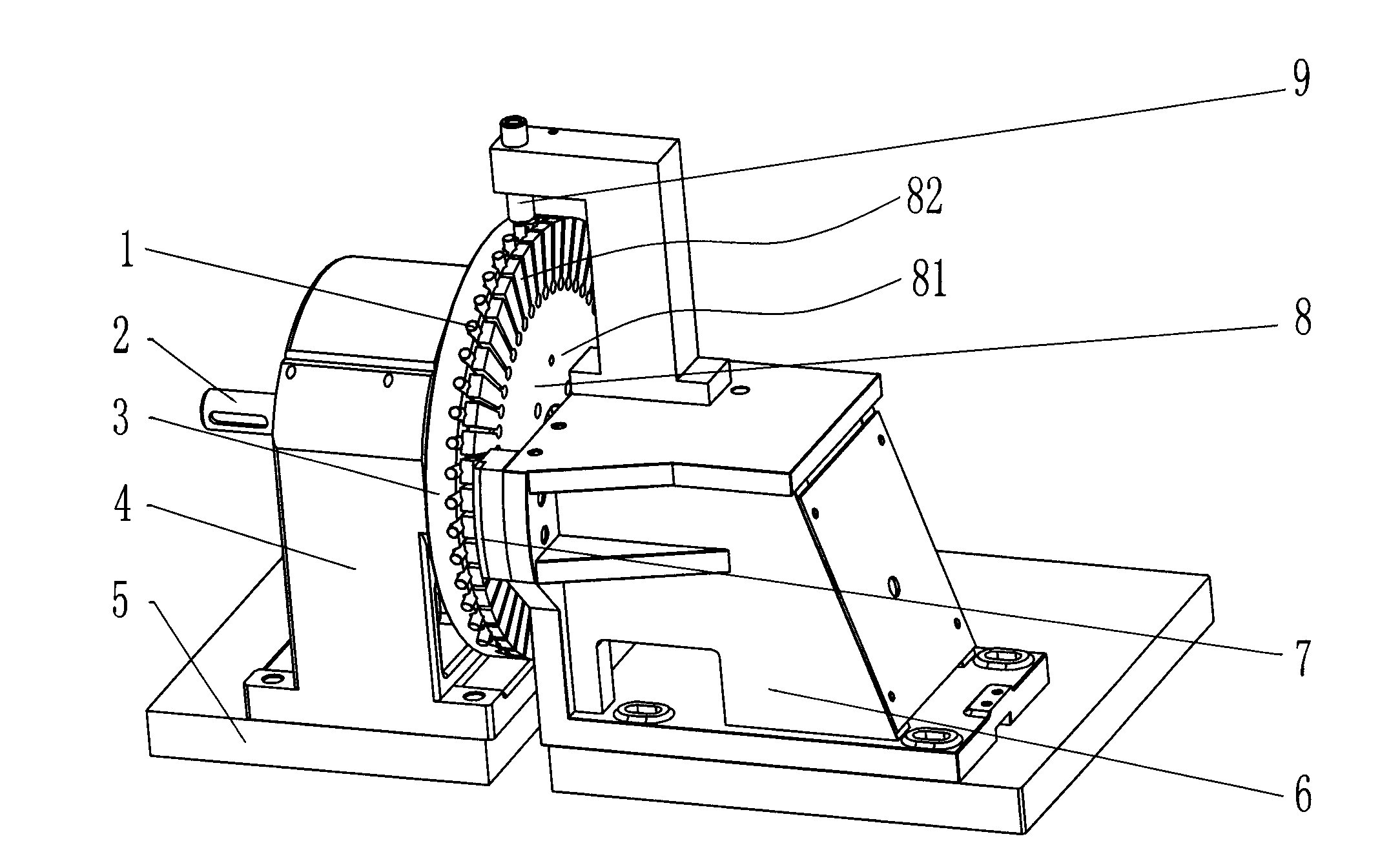
[0033] Such as Figure 1-3 Shown: a material guide and clamping device for processing workpieces, including: a clamping disc 3, a rotating shaft 2 that drives the clamping disc 3 to rotate, a shaft seat 4, and a pressing block matched with the clamping disc 3 7. The pressing block mounting seat 6 and the power source; characterized in that: a multi-elastic sheet pressing plate 8 is provided between the clamping disc 3 and the pressing block 7, and the multi-elastic sheet pressing The disc 8 rotates synchronously with the clamping disc 3, and is mainly composed of a base 81 and an elastic sheet 82 connected around the base.

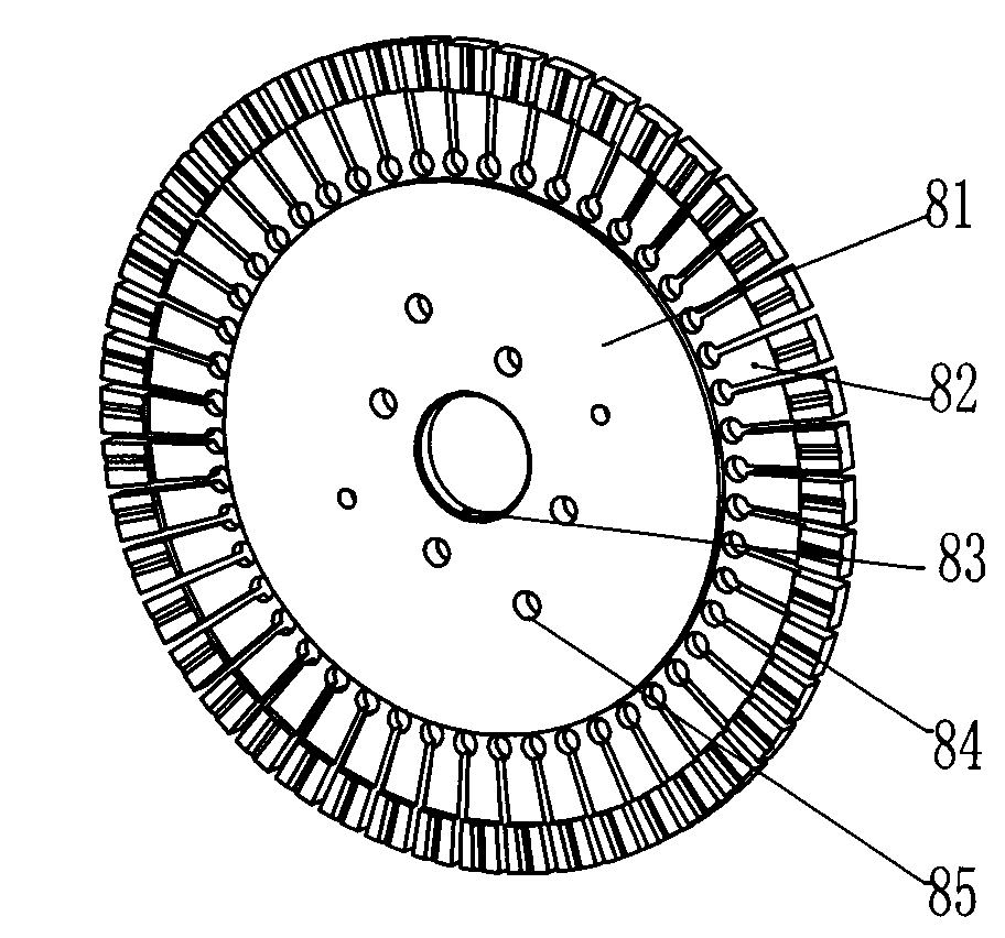
[0034] The multi-elastic sheet pressing plate 8 is coaxially installed with the clamping disc 3, and includes: a base 81, a plurality of elastic sheets, each corresponding to the position of the processing workpiece 1 on the clamping disc 3 82. Fix the multi-elastic sheet press plate 8 to the fixing screw hole 85 on the clamping disc 3. The multi-elastic sh...

Embodiment 2

[0039] The structure of Example 2 is basically the same as that of Example 1 (the figure is omitted). The multi-elastic sheet pressing plate is mainly composed of a base body and an elastic sheet connected around the base body ( Figure 4 , 5 ), the elastic sheet 82 is provided with a shaping groove 84 for clamping the processed workpiece, and the central hole 83 is not set in the center, and is fixed by a fixing screw hole 85.

Embodiment 3

[0041] The structure of Example 3 is basically the same as that of Example 1 (the figure is omitted). The multi-elastic sheet pressing plate is mainly composed of a base body and an elastic sheet connected around the base body ( Image 6 , 7 ), the center is provided with a positioning center hole 83, and the elastic sheet 82 is not provided with a shaping groove 84 for clamping the workpiece. In this case, the elastic piece 82 cooperates with the "V" shaped groove on the clamping disc to clamp the workpiece.


PUM


Abstract

The invention relates to the technical field of clamping when cylindrical hardware and screws are processed, in particular to a device for guiding and clamping a workpiece when the cylindrical hardware and the screws are processed. The device for guiding and clamping the workpiece comprises a clamping disc, a rotating shaft, a shaft seat, a pressing block, a pressing block installing seat and a power source, wherein the rotating shaft drives the clamping disc to rotate; and the pressing block is matched with the clamping disc. The device is characterized in that a plurality of elastic sheet pressing discs are arranged between the clamping disc and the pressing block and can rotate synchronously with the clamping disc; and each elastic sheet pressing disc mainly comprises a base body and an elastic sheet connected at the periphery of the base body. In the device, not only the product quality can be guaranteed, but also the production efficiency can be guaranteed, the labor and the time are saved, so that energy conservation and consumption reduction are realized, the production cost is reduced, and especially, the damage of the pressing block to a processing workpiece in processing is avoided so as to solve the problem which is wanted for being solved for years and has been not solved yet in the industry cycle.

Description

Technical field [0001] The invention relates to the technical field of clamping for cylindrical hardware and screw processing, in particular to a device for guiding and clamping a workpiece during cylindrical hardware and screw processing. It is an automated slot milling machine, a punching machine, etc. Important parts of machine tools. Background technique [0002] Nowadays, the machining process of slotted set screws (a slotted screw at the end without a head) is to first cut the material, then roll the thread, and then mill the slot. In the implementation of milling grooves, the rotating chuck of the station is usually used for clamping, and then the fixed pressing block is used for pushing and processing. This type of clamping will produce friction between the workpiece and the fixed pressing block during the processing, and the workpiece will produce compression marks after the processing is completed. These compression marks will cause the appearance of the screw that ha...

Claims


Application Information

Patent Timeline
IPC IPC(8): B23Q7/02
Inventor 罗锡锋
Owner 罗锡锋
Why Eureka
Try Eureka