
Integral detection cabinet with battery cabin

A technology of battery detection and battery compartment, which is applied to the parts of electrical measuring instruments, measuring electricity, measuring devices, etc., can solve problems such as unfavorable battery heat dissipation, affecting test results, battery damage, etc., to prolong the service life of mechanical positioning, improve the Heat dissipation capacity, the effect of preventing the impact of the battery

Active Publication Date: 2011-07-13
REPOWER TECH CO LTD
View PDF7 Cites 17 Cited by
  • Summary
  • Abstract
  • Description
  • Claims
  • Application Information

AI Technical Summary

Problems solved by technology

[0002] In the prior art battery testing cabinet, the battery is placed in the battery drawer or tray at the lower end of the testing cabinet, or in other battery storage containers, and then the battery is connected to the battery testing device for charging and discharging testing. This kind of battery tray or container does not have a tank that separates the battery from the battery, so that multiple batteries are placed in the tray chaotically during use, and the connecting wires are easily intertwined and intertwined. Correspondingly, it brings unnecessary trouble to the test. In addition, the tray is usually not conducive to battery heat dissipation. The battery generates heat during charging / discharging. The heat accumulation will affect the test results and may cause battery damage, which is not conducive to the safety of battery testing. performance, heat dissipation of the battery, and the electrical connection between the battery detection charging and discharging unit and the battery drawer or tray are all connected by wires, so a large number of wires are needed, and the battery drawer or tray needs to move back and forth. The cables and wires connecting the charging and discharging unit to the drawer or tray will be aged or broken

Method used


Image

  • Integral detection cabinet with battery cabin
  • Integral detection cabinet with battery cabin
  • Integral detection cabinet with battery cabin

Examples


Embodiment Construction

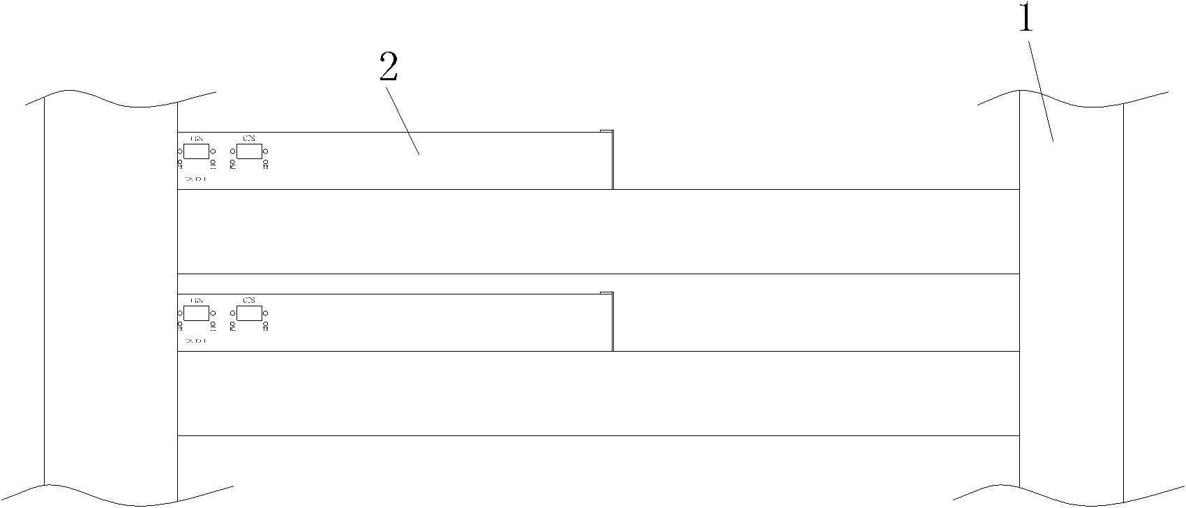
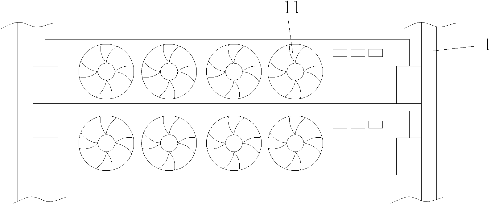
[0023] The present invention will be further described in detail below with reference to the drawings and embodiments. Such as figure 1 with figure 2 As shown, in the integrated detection cabinet with battery compartment of the present invention, the cabinet frame 1 is composed of four uprights and upper and lower panels. The rectangular cabinet frame 1 is provided with drawers arranged in layers from top to bottom. The battery detection device 2 has a push-pull structure. The shape of the battery detection device 2 is rectangular. The front end of the battery detection device 2 is connected with a battery compartment 3 integrated with the battery detection device 2 and on the same level. The battery compartment 3 has no cover on the top. The rectangular box body is made of a metal material with a thickness of 1.0-1.2mm, the exterior is sprayed, and the interior is insulated with PVC coating. The front-to-back depth dimension of the battery detection device 2 is shorter than t...


PUM


Abstract

The invention discloses an integral detection cabinet with a battery cabin. The technical problem needing to be solved is to save a placing space of the battery cabin, improve the heat dissipation capability, reduce the drop and breakage rate of connection wires and prolong the service life of the detection cabinet. The technical scheme of the invention is that: the integral detection cabinet with the battery cabin is provided with a cabinet frame, the cabinet frame is provided with a battery detection device with a pushing-pulling structure; the battery cabin is connected with the front end of the battery detection device; a tray is arranged in the battery cabin; clapboards are arranged in the tray in parallel; every two clapboards form a groove; plugs are arranged on a front panel of the battery detection device above the groove respectively; and a first radiating hole is arranged at a rear side plate of the battery cabin. Compared with the prior art, the drop and breakage rate of the connection wires caused by pushing and pulling many times is reduced, the mechanical location service life of the battery detection cabinet is prolonged, the space for placing the battery in the battery cabin is saved, the radiation capacity is improved and the reliable connection between the batteries and a charging port is ensured.

Description

Technical field [0001] The invention relates to a detection device in a battery manufacturing process, in particular to an integrated detection cabinet for detecting battery charging / discharging. Background technique [0002] In the prior art battery detection cabinet, the battery is placed in the battery drawer or tray at the lower end of the detection cabinet, or in other battery storage containers, and then the battery is connected to the battery detection device for charging and discharging detection. This kind of battery tray or container does not have a slot for separating the battery from the battery, so that multiple batteries are placed chaotically in the tray during use, and the connecting wires are easily intertwined. It is not convenient to accurately connect the battery to the test contact during the test. Correspondingly, it brings unnecessary trouble to the detection. In addition, the tray is usually not conducive to the heat dissipation of the battery. The battery...

Claims


Application Information

Patent Timeline
Patent Type & Authority Applications(China)
IPC IPC(8): G01R31/36G01R1/02H05K7/20
Inventor 毛广甫
Owner REPOWER TECH CO LTD
Learn More