System and method for testing chip voltage signal
A voltage signal and test system technology, applied in the direction of measurement using digital measurement technology, can solve problems such as time-consuming cost, complex detection circuit, etc., and achieve the effects of saving chip area, simplifying test methods, and simple circuits
- Summary
- Abstract
- Description
- Claims
- Application Information
AI Technical Summary
Problems solved by technology
Method used
Image
Examples
Embodiment Construction
[0043] The principles and features of the present invention are described below in conjunction with the accompanying drawings, and the examples given are only used to explain the present invention, and are not intended to limit the scope of the present invention.
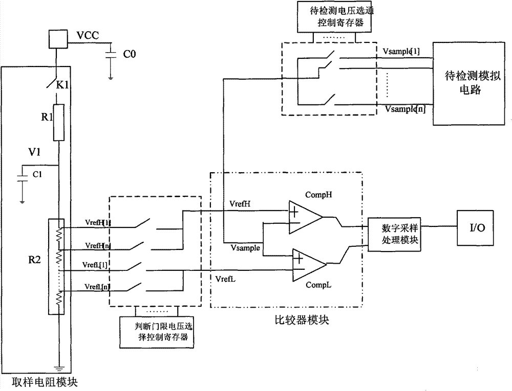
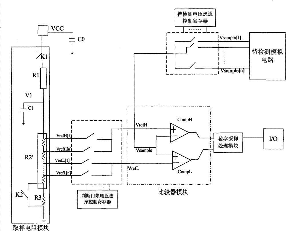
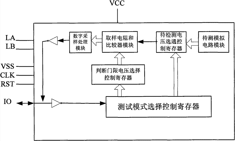
[0044] Such as figure 1 with figure 2 As shown, the test system of the chip voltage of the present invention mainly includes a sampling resistor module, a judgment threshold voltage selection control register, a voltage to be detected gating control register, a comparator module, a digital sampling processing module and a test mode selection control register, and each of the above-mentioned The modules are electrically connected together to form a detection system.
[0045] One end of the sampling resistor module is connected to the power supply voltage VCC, specifically through the chip PAD and VCC, preferably a capacitor C0 is provided at the VCC end to filter out most of the power supply ripple. Capacitor C0 s...
PUM
 Abstract
Description
Claims
Application Information
 - R&D
- Intellectual Property
- Life Sciences
- Materials
- Tech Scout
- Unparalleled Data Quality
- Higher Quality Content
- 60% Fewer Hallucinations
Browse by: Latest US Patents, China's latest patents, Technical Efficacy Thesaurus, Application Domain, Technology Topic, Popular Technical Reports.
© 2025 PatSnap. All rights reserved.Legal|Privacy policy|Modern Slavery Act Transparency Statement|Sitemap|About US| Contact US: help@patsnap.com


