
Multi-head machine thread stand of computerized embroidery machine

A technology for embroidery machines and multi-head machines, which is applied in the field of multi-head machine thread racks, which can solve the problems of multiple threads being entangled or knotted, paralleled, and entangled, and achieve the effect of convenient threading

Inactive Publication Date: 2011-07-06
DONGYANG JIALUN ELECTRONICS MACHINERY
View PDF4 Cites 4 Cited by
  • Summary
  • Abstract
  • Description
  • Claims
  • Application Information

AI Technical Summary

Problems solved by technology

[0006] The purpose of the present invention is to overcome the disadvantages of the multi-head thread stand structure of the prior art computerized embroidery machine that it is easy to make multiple threads intertwined or knotted to cause problems such as thread merging and thread breakage, and to provide a thread that can go out smoothly, Multi-head thread frame for computerized embroidery machines that can prevent air convection on the frame from thread doubling, winding or knotting.

Method used


Image

  • Multi-head machine thread stand of computerized embroidery machine
  • Multi-head machine thread stand of computerized embroidery machine
  • Multi-head machine thread stand of computerized embroidery machine

Examples


Embodiment 1

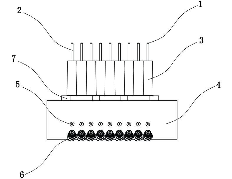
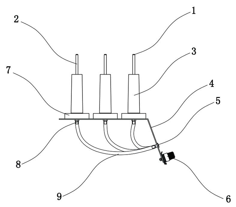
[0022] Embodiment 1: as figure 2 As shown, a multi-head thread frame of a computerized embroidery machine includes a base plate 4. The base plate 4 has a horizontal plane in the horizontal direction and an inclined plane connected to one side of the horizontal plane and opens obliquely downward and outwardly. The base plate 4 is provided with Multiple sets of thread racks including thread spool 3, thread seed 1 and thread gripper 6.

[0023] Such as image 3 As shown, the single group of wire racks includes a wire-passing pipe 2 arranged upright on a horizontal plane above the substrate 4, and a through hole 8 is provided on the substrate 4 where the lower end of the wire-passing pipe 2 is connected to the substrate 4. The pipelines of the line pipe 2 are connected, and a thread nut is installed on the through hole 8 . The upper end of the thread pipe 2 is provided with a thread seed 1 . A thread gripper 6 is provided on the lower inclined surface of the substrate 4, and a...


PUM


Abstract

The invention discloses a multi-head machine thread stand of a computerized embroidery machine. The multi-head machine thread stand comprises a base plate; multiple groups of thread stands are arranged on the base plate; each group of thread stands comprises threading pipes vertically distributed above the base plate; a through hole is formed on the base plate at the joint of the lower end of each threading pipe and the base plate; the through holes are communicated with the threading pipes; a threading seed is arranged at the upper end of each threading pipe; a thread clamping device is arranged on the lower side of the base plate; a thread hole is formed on the base plate between the thread clamping device and the through holes; and the pipe body of each threading pipe is sleeved by a thread cylinder. In the whole threading process, embroidery threads coming out of all the thread cylinders are bounded by the threading seeds, the threading pipes, the through holes, the thread holes and the thread clamping device in sequence, each embroidery thread almost passes through an individual channel, and slack thread sections exposed outside are short, so that the threads can hardly be influenced by the external world, particularly the wind power. The multi-head machine thread stand can well prevent the problem of thread doubling, winding or knotting caused by air convection during the threading of the multi-head machine thread stand.

Description

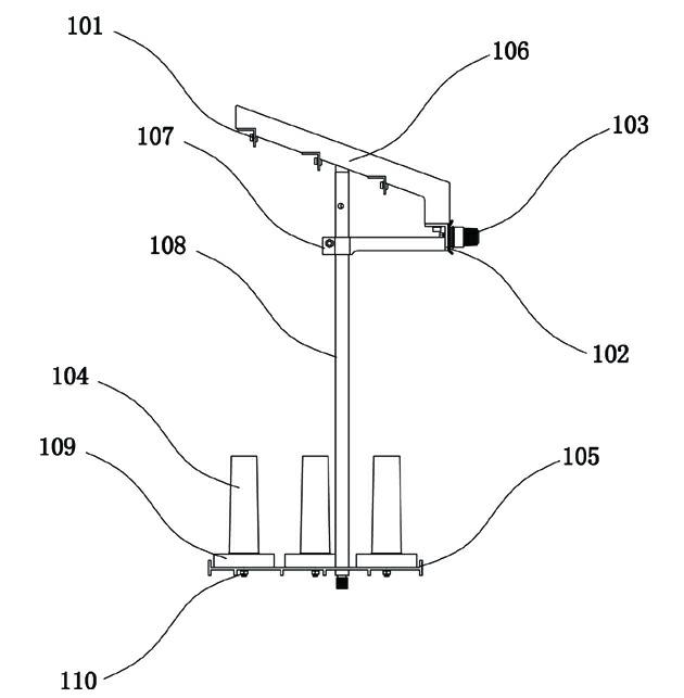
[0001] technical field [0002] The invention relates to the technical field of embroidery machine thread stands, more specifically a multi-head thread stand for computerized embroidery machines. Background technique [0003] Most of the existing multi-head computerized embroidery machine thread frame structures are as follows: figure 1 As shown, it includes a base plate 105 and a support beam 106. A support bar 108 is arranged upright on the base plate 105. The support beam 106 is arranged obliquely and fixed on the top of the support bar 108 below its middle. The support beam 106 is also The fixing is strengthened by the reinforcing bar 107; the base plate 105 is installed on the main beam of the computerized embroidery machine, and the base plate 105 and the support beam 106 are correspondingly provided with multiple groups of thread rack components. The single-group wire frame includes a wire insertion nail 110 installed on the base plate 105, and a plastic wire inser...

Claims


Application Information

Patent Timeline
Patent Type & Authority Applications(China)
IPC IPC(8): D05C11/00
Inventor 邵金鹏吴高阳胡志清蒋庆丰赵洪海胡鸳鸳
Owner DONGYANG JIALUN ELECTRONICS MACHINERY
Learn More