
Method for welding conductive copper foil for whole satellite grounding network

A welding method and technology of grounding grid, applied in welding equipment, resistance welding equipment, metal processing equipment, etc., can solve the problem that the design requirements of conductive copper foil lap resistance can no longer be met, and the resistance value of conductive copper foil lap resistance exceeds the standard. , the grounding resistance cannot meet the design requirements, etc., to achieve the effect of safe and effective electrostatic protection measures, improve the stability of electrostatic protection, and have no hidden quality safety hazards

Inactive Publication Date: 2011-07-06
BEIJING INST OF SPACECRAFT ENVIRONMENT ENG
View PDF5 Cites 3 Cited by
  • Summary
  • Abstract
  • Description
  • Claims
  • Application Information

AI Technical Summary

Problems solved by technology

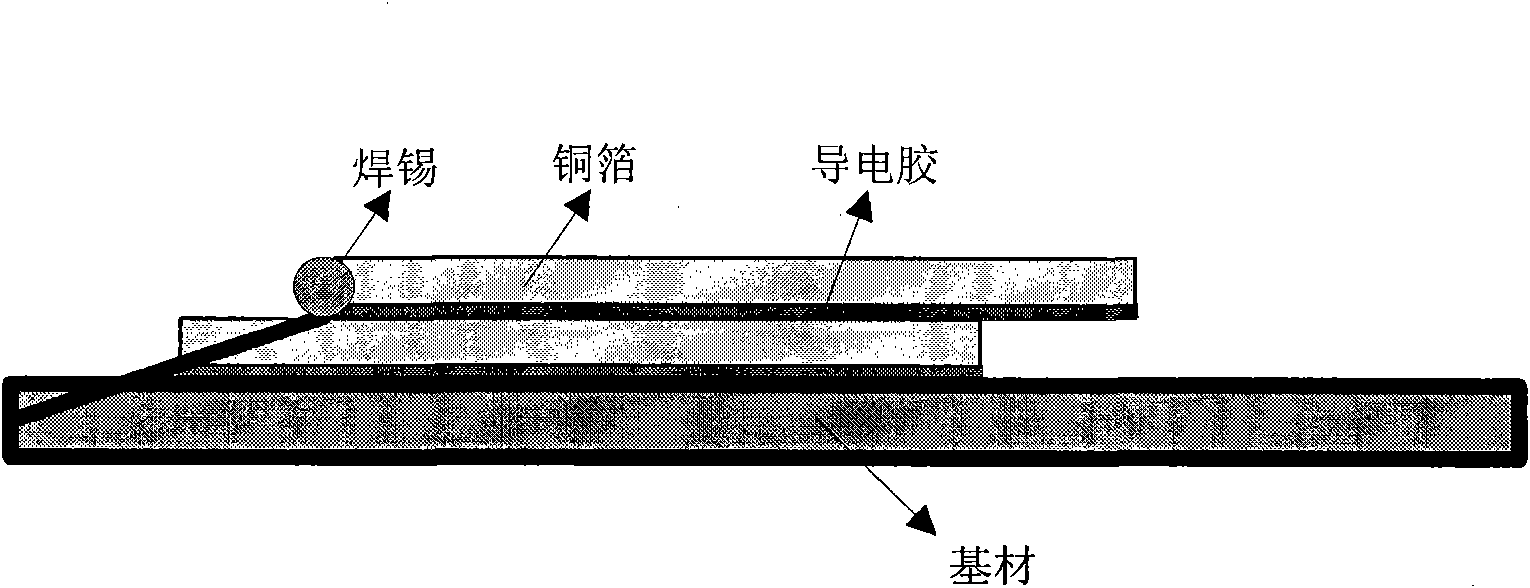
However, in the process of building the grounding grid, it is often found that the grounding resistance cannot meet the design requirements. One of the reasons that cannot be ignored is that the resistance value of the conductive copper foil lapping resistance exceeds the standard with the assembly cycle. For example, see figure 1 , the traditional conductive copper foil is realized by pasting the conductive copper foil on the substrate sequentially through conductive glue
However, the resistance degradation of the conductive adhesive directly leads to the degradation of the contact resistance of the conductive copper foil, which can no longer meet the design requirements of the lap resistance of the conductive copper foil in the satellite assembly process. Required Conductive Copper Foil Soldering Method

Method used


Image

  • Method for welding conductive copper foil for whole satellite grounding network
  • Method for welding conductive copper foil for whole satellite grounding network
  • Method for welding conductive copper foil for whole satellite grounding network

Examples


Embodiment Construction

[0020] The specific embodiment of the present invention is further described below in conjunction with accompanying drawing:

[0021] refer to figure 2 , the welding method of conductive copper foil for whole star grounding grid of the present invention, comprises the following steps: a) a copper foil is pasted on the base material by conductive glue, after being pasted on the copper foil of the base material by conductive glue Paste another copper foil indentedly; b) spot-weld the front end of the other copper foil that is indented and the copper foil pasted on the base material by soldering. The thickness of the conductive copper foil is 0.066mm. Usually, when the surface of the conductive copper foil is not polished, the contact resistance is greater than 10mΩ. When the contact surface is sufficiently polished, the contact resistance is significantly reduced to about 3.5mΩ. Reduced to below 3mΩ, for example around 2.7mΩ. Preferably, the contact surface of the conductive...


PUM

PropertyMeasurementUnit
Thicknessaaaaaaaaaa

Abstract

The invention discloses a method for welding a conductive copper foil for a whole satellite grounding network, which comprises the following steps of: a) adhering the copper foil to a substrate by using a conductive adhesive, and adhering the other copper foil to the copper foil adhered to the substrate by using the conductive adhesive in a mode of backward indention; and b) performing spot welding on the front end of the other indented copper foil and the copper foil adhered to the substrate. A surface spot welding method of the conductive copper foil for the whole satellite grounding network is simple in implementation, and ensures that a potential quality safety hazard is avoided and the lap resistance of the conductive copper foil is reduced obviously to be below 3 megohms. The grounding performance of the whole satellite grounding network in the period of final assembly of a satellite is stable and not degraded, and static protection measures are safe and effective and meet requirements of design indexes.

Description

technical field [0001] The invention relates to the field of resistance degradation of conductive copper foils for whole-satellite grounding grids, in particular to a resistance welding method for conductive copper foils for whole-stationary grounding grids. Background technique [0002] Electrostatic discharge (ESD) is a pervasive electromagnetic compatibility problem that can cause electronic equipment to malfunction or cause damage. The instantaneous high current caused by electrostatic discharge can ignite and detonate flammable and explosive gas mixtures or electrical explosives, resulting in accidental combustion and explosion accidents; the Coulomb force of the electrostatic field makes the instrument and equipment unable to work normally; the electromagnetic radiation of electrostatic discharge or Various accidents caused by electromagnetic interference caused by electrostatic discharge electromagnetic pulses to electronic equipment. [0003] There are many electron...

Claims


Application Information

Patent Timeline
IPC IPC(8): B23K11/11
Inventor 路毅熊涛卫月娥杨前进贺文兴刘孟周黄磊乔敏李振丽李秀珍李东
Owner BEIJING INST OF SPACECRAFT ENVIRONMENT ENG
Learn More