Dishwasher with rotary cage
A dishwasher and rotating cage technology, which is applied to the washing machine/washing machine for tableware, the parts of the washing machine/rinsing machine for tableware, cleaning equipment, etc., can solve the problem of insufficient cleaning, long cleaning time, water consumption and power consumption Many other problems, to achieve the effect of thorough cleaning, short time-consuming and fast cleaning
- Summary
- Abstract
- Description
- Claims
- Application Information
AI Technical Summary
Problems solved by technology
Method used
Image


Examples
Embodiment 1
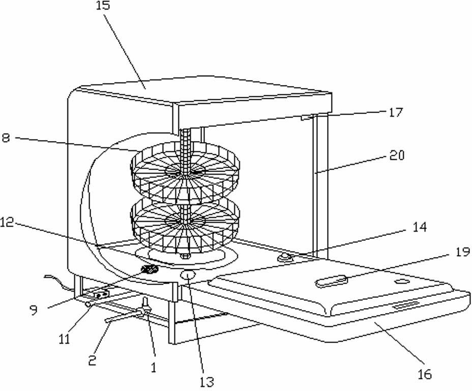
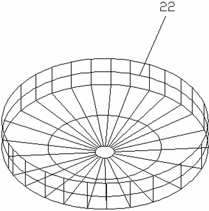
[0042] Embodiment 1: as Figure 5 As shown, the tumbler 8 is braided and welded by stainless steel wire, and is composed of upper, middle and lower layers, that is, three bowl racks 22. The water spray pipe 7 is rectangular, and a part of the water spray pipe 7 is fixed on the inner wall of the box body 15 and the inner top. On the wall, another part of the water spray pipe 7 is bent into a rectangle and surrounds the rotating cage 8; the black single arrow in the figure indicates the water flow and direction ejected from the nozzle, and the semicircular arrow indicates the direction of rotation of the rotating cage 8; in the rotating cage 8, there are bowls, Demonstration of how to place dishes and plates, the same below.
Embodiment 2
[0043] Embodiment 2: as Figure 6 Shown, this rotating cage 8 is made up of two bowl racks of two layers, and bowl rack 22 is movable type, and the user can increase or decrease bowl rack as required; and the upper side are fixed on the inner side wall and the inner top wall of the casing 15, and the remaining parts surround the rotating cage 8 and have a notch in the upper right corner. The user can increase or decrease from the notch according to the actual situation and the number of dishes to be washed. Fewer dish racks. The black single arrow in the figure indicates the water flow and direction ejected from the nozzle, and the semicircular arrow indicates the direction of rotation of the rotating cage 8.
Embodiment 3
[0044] Embodiment 3: as Figure 7 Shown, the rotating cage 8 of this embodiment 3 does not rotate around the water spray pipe 7 but rotates with its central axis 27; Be bearing or speed changer 21 between the outer walls, and rotating cage 8 rotates with central axis under the effect of spraying water, and a vertical limit of water spraying pipe 7 is fixed on casing 15 inwalls, and the bottom surface of other three limits and bowl rack 22 are parallel to each other. The black single arrow in the figure indicates the water flow and direction sprayed by the nozzle, and the semi-circular arrow indicates the rotation direction of the cage.
PUM
 Abstract
Description
Claims
Application Information
 - R&D
- Intellectual Property
- Life Sciences
- Materials
- Tech Scout
- Unparalleled Data Quality
- Higher Quality Content
- 60% Fewer Hallucinations
Browse by: Latest US Patents, China's latest patents, Technical Efficacy Thesaurus, Application Domain, Technology Topic, Popular Technical Reports.
© 2025 PatSnap. All rights reserved.Legal|Privacy policy|Modern Slavery Act Transparency Statement|Sitemap|About US| Contact US: help@patsnap.com