
Line control method in optical network and optical network itself

A line control, optical network technology, applied in the field of optical access network, can solve the problem of line privacy limit, increase the maximum distance of accommodating users, etc., and achieve the effect of extending the maximum distance

Inactive Publication Date: 2011-06-29
KEIO UNIV
View PDF5 Cites 5 Cited by
  • Summary
  • Abstract
  • Description
  • Claims
  • Application Information

AI Technical Summary

Problems solved by technology

Therefore, there is a limit in principle to increasing the number of accommodated users for one OLT or extending the maximum distance
In addition, in GE-PON, since all optical signals reach all ONUs, there is also a limit in principle regarding line privacy

Method used


Image

  • Line control method in optical network and optical network itself
  • Line control method in optical network and optical network itself
  • Line control method in optical network and optical network itself

Examples


Embodiment Construction

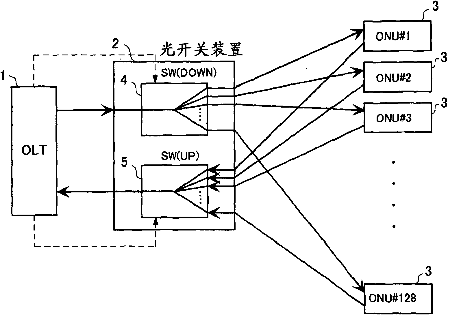
[0039] figure 1 It is a functional block diagram showing the configuration of an embodiment of the optical network of the present invention.

[0040] In this figure, 1 is an optical line terminal (OLT), 2 is an optical switch device, and 3 is a plurality of terminal devices (ONU: Optical Network Unit) connected in parallel to the optical switch device 2 . As shown in the figure, a tree structure with OLT1 as the vertex is formed, and multiple ONU3s are connected downstream. An active optical switch device 2 is provided between the OLT1 and the ONU3. The optical fibers connecting these structural elements maintain compatibility with the aforementioned GE-PON, and perform transmission at downstream 1490nm and upstream 1310nm. In addition, it is assumed that the optical switch device 2 is installed in a facility under the jurisdiction of a carrier by extending the maximum distance, and it is assumed that the OLT 1 ​​and the optical switch device 2 are synchronized.

[0041] T...


PUM


Abstract

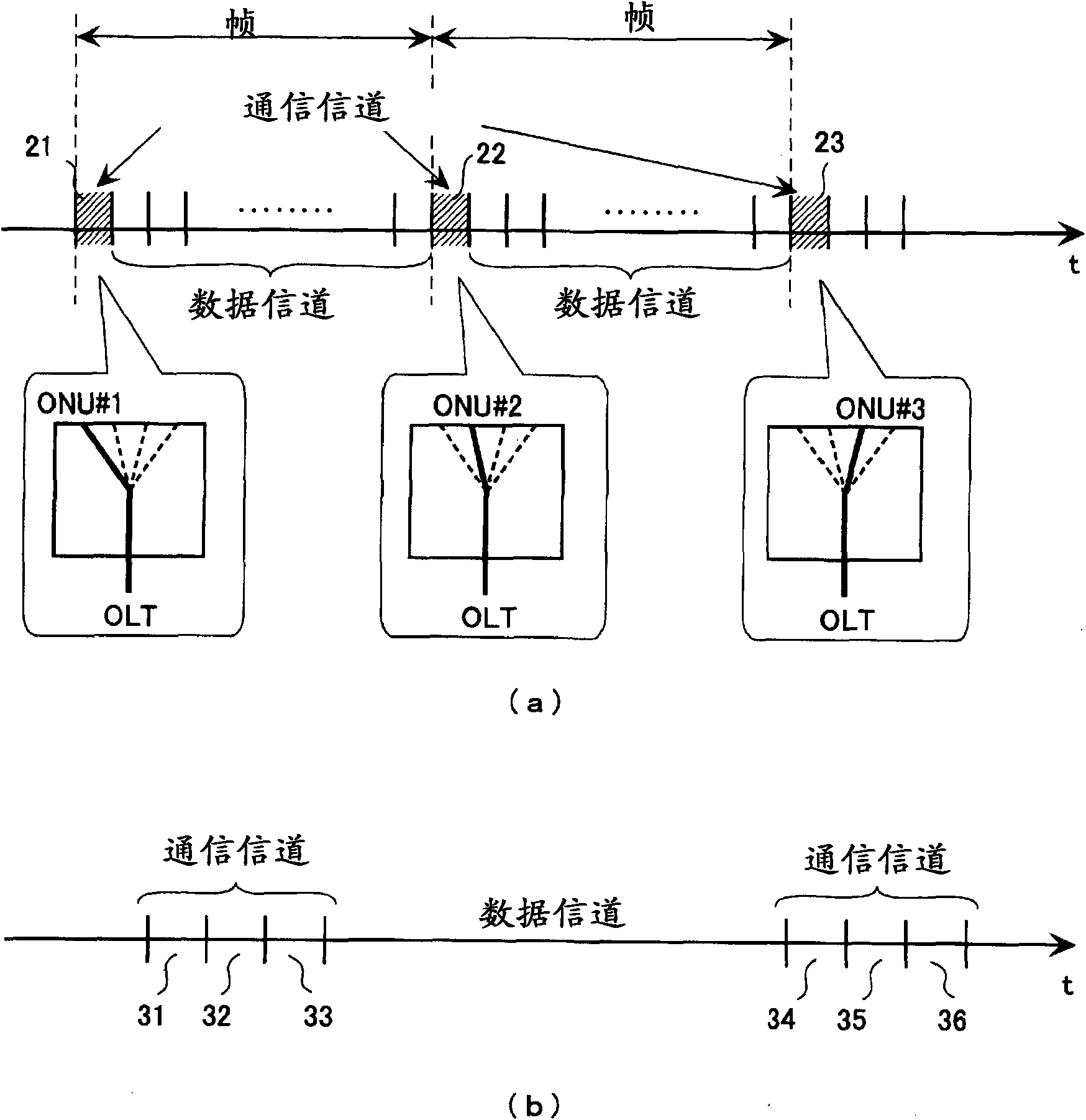
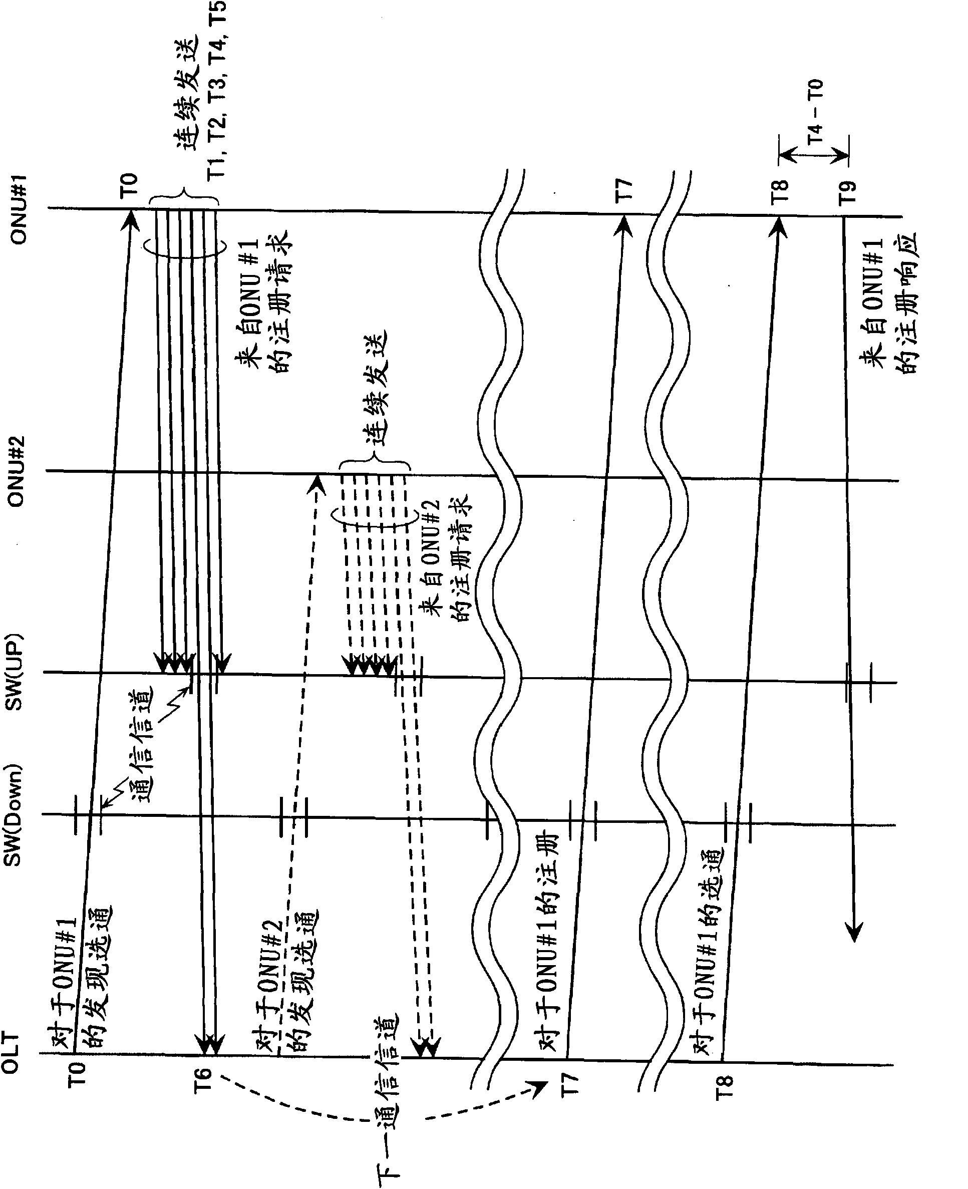
It is possible to establish a communication between an OLT and an ONU in an access network using an optical switch without requiring photoelectrical conversion by an optical switch unit. The OLT successively selects an ONU in slots discretely arranged by controlling a downlink optical switch SW(DOWN) and transmits a Discovery Gate message. The ONU which has received the Discovery Gate continuously transmits a Register Request message. An uplink optical switch SW(UP) successively switches signals from ONU#1 to ONU#128 from one to another in the slots discretely arranged and outputs the signalsto the OLT. Some of the Register Requests transmitted from the respective ONUs reach the OLT through the SW(UP). The OLT decides the ONU transmission timing in accordance with the received Register Request and reports the timing by a Gate message.

Description

technical field [0001] The invention relates to an optical access network such as FTTH (Fiber to the Home, fiber to the home) which connects the user's network and the accommodation office of the communication operator by optical fiber. Background technique [0002] In current FTTH, a passive optical access network called GE-PON (Gigabit Ethernet-Passive Optical Network, Gigabit Ethernet-Passive Optical Network) is used. [0003] Figure 5 It is a figure which shows the structure of GE-PON. [0004] As shown in the figure, GE-PON is composed of an OLT (Optical Line Terminal: local end device) 51, a splitter 52, and a plurality of ONUs (Optical Network Unit: terminal device) 53, forming a tree with the OLT 51 as the vertex. [0005] The downstream signal from the OLT51 is duplicated by the splitter 52 and sent to all the ONU53. The ONU 53 discards frames other than its own with reference to LLID (Logical Link ID) in the preamble. On the other hand, since the upstream signa...

Claims


Application Information

Patent Timeline
Patent Type & Authority Applications(China)
IPC IPC(8): H04L12/44H04B10/20H04Q3/52H04B10/00H04B10/272
CPCH04Q2011/0064H04Q2011/0079H04Q2011/0041H04Q11/0067H04Q2011/0088H04L12/2869
Inventor 山中直明荒川豊德桥和将
Owner KEIO UNIV
Learn More